Product Description
OEM CNC Machining Split Motor Rigid Shaft Coupling
Product Description
|
Customized cnc machining parts notes: |
||||
|
Quotation |
According to your drawing(size, material, thickness, processing content, and required technology, etc) |
|||
|
Tolerance Surface Roughness |
+/-0.02 – 0.01mm Ra0.2 – Ra3.2(Customized avaiable) |
|||
|
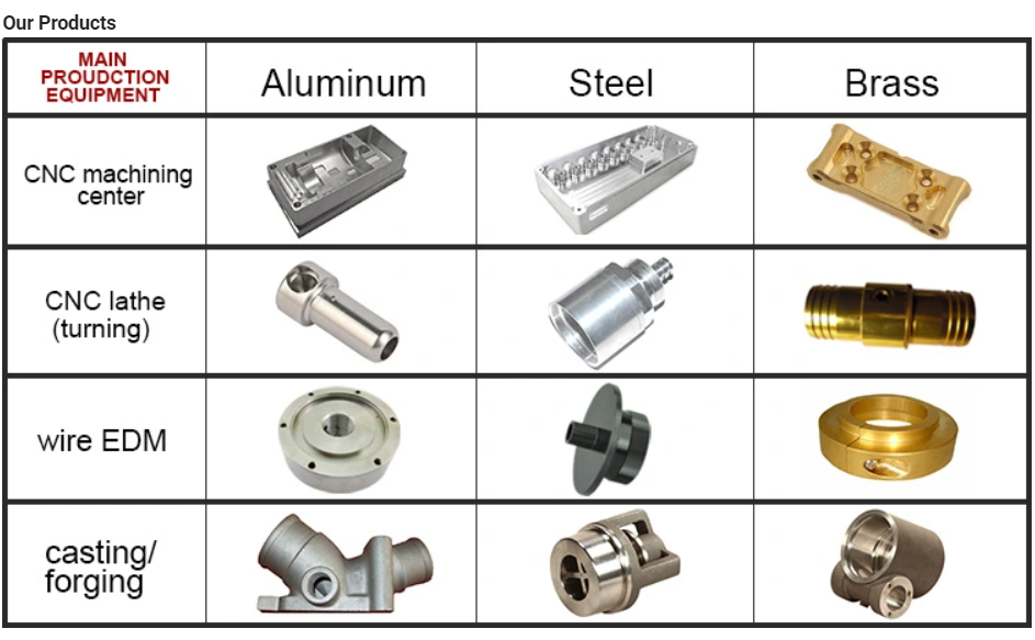
Materials Avaiable |
Aluminum, Copper, Stainless steel, Iron, PE, PVC, ABS, etc. |
|||
|
Surface Treatment |
Polishing, general/hard/color oxidation, surface chamfering, tempering, etc. |
|||
|
Processing |
CNC Turning, Milling parts, drilling, auto lathe, tapping, bushing, surface treatment, etc. |
|||
|
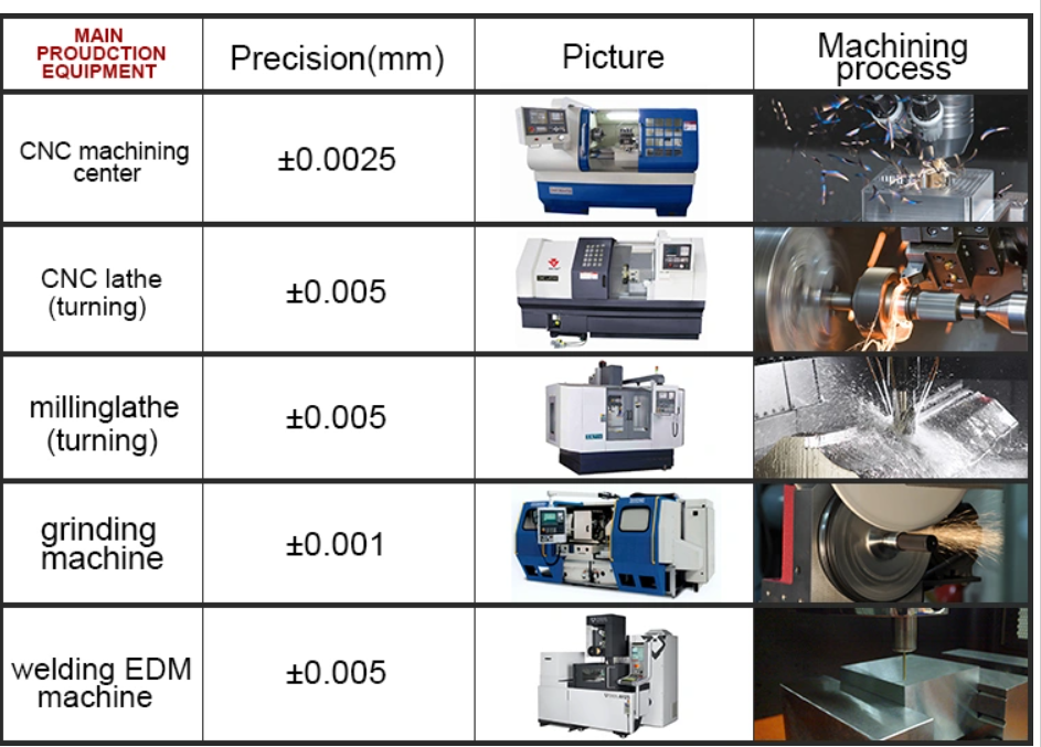
Testing Equipment |
CMM/Tool microscope/multi-joint arm/Automatic height gauge/Manual height gauge/Dial gauge/Roughness measurement |
|||
|
Drawing Formats |
PRO/E, Auto CAD, CHINAMFG Works , UG, CAD / CAM / CAE, PDF PRO/E, Auto CAD, CHINAMFG Works , UG, CAD / CAM / CAE, PDF |
|||
|
Our Advantages |
(1) 24 hours online service & Quickly Quote/Delivery. (2) 100% QC quality inspection before delivery, and can provide quality inspection form. |
|||
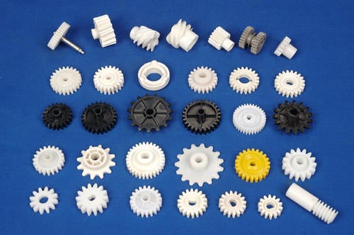
Features of jaw coupling:
1.Easy of inspection,easy maintenance.
2.Can absorb vibration,parallel,angular and axial misalignments.
3.Identical clockwise and anticlockwise rotational charateristics.
4.Both ends material is iron, intermediate for rubber materials.
5.Simple configuration, setscrew type,low price.
6.Hole can be self-processing,easy facilitate.
7.For step motor,screw, machine positioning system.
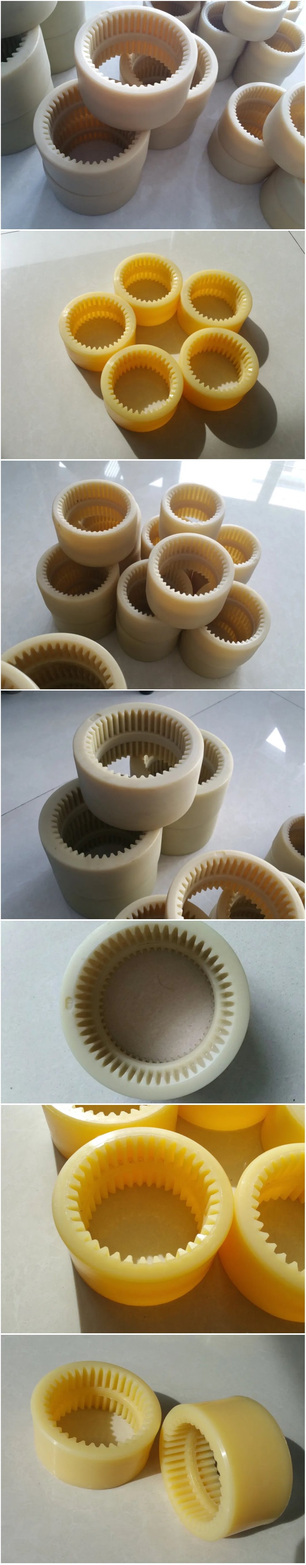
The SL cross slide coupling is slid in the corresponding radial grooves of the large end faces
of the half couplings on both sides.
The main feature of the slider coupling is that it allows the 2 shafts to have a large radial
displacement, and allows for small angular displacement and axial displacement. Due to the
centrifugal force generated by the eccentric motion of the slider, it is not suitable to use this
coupling. High-speed movement, the coupling torque of the coupling is 120-63000N.m, the
speed is 250-70r/min.
Advantages:
Protects driven component by serving as a mechanical “fuse” – an inexpensive replaceable plastic
midsection shears under excess load.
Protects support bearings by exerting consistently low reactive forces, even under large misalignments.
Homokinetic transmission – driving and driven shafts rotate at exactly the same speed at all times.
Zero backlash and high torsional stiffness.
Accommodates large radial misalignment in a short length.
Easy installation in blind or difficult installations when through-bores are used.
Economically priced compared to other couplings with similar performance characteristics.
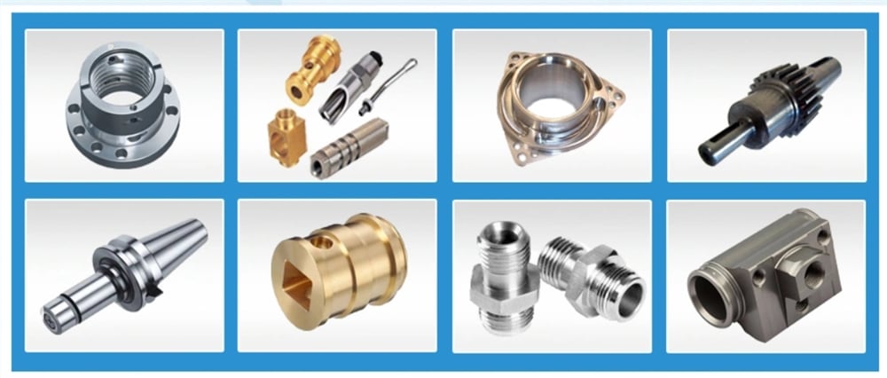
CNC machining parts, metal machining parts, precision machining parts, Machined parts, Machinery
parts,Machine Parts,machining parts machining,Cnc machining parts machinery parts,machined
parts,precision machining parts,oem machining parts,cnc machining parts,cnc machined parts.
Q: Why choose Shengao product?
A: We shengao have our own plant– HangZhou Shengao machinery Co.,Ltd, therefore, we can
surely promise the quality of every product and provide you comparable price.
Q: Do you provide OEM Service?
A: Yes, we provide OEM Service.
Q: Do you provide customized machining parts?
A: Yes. Customers give us drawings and specifications, and we will manufact accordingly.
Q: What is your payment term?
A: We provide kinds of payment terms such as L/C, T/T, Paypal, Escrow, etc.
If there’s anything we can help, please feel free to contact with us. /* March 10, 2571 17:59:20 */!function(){function s(e,r){var a,o={};try{e&&e.split(“,”).forEach(function(e,t){e&&(a=e.match(/(.*?):(.*)$/))&&1

What are the potential drawbacks or limitations of using rigid shaft couplings in certain applications?
Rigid shaft couplings, while offering benefits in certain scenarios, also have limitations that should be considered when selecting them for specific applications:
- Minimal Misalignment Compensation: Rigid couplings have limited ability to compensate for shaft misalignment, making them less suitable for applications with significant misalignment.
- Transmits Vibrations: Rigid couplings do not dampen vibrations, which can lead to increased wear and fatigue in connected components and decrease overall system lifespan.
- Higher Stress Concentration: Due to their rigid nature, these couplings can result in higher stress concentrations at the coupling ends, potentially leading to premature failure.
- Noisy Operation: Rigid couplings can amplify noise generated by connected equipment, contributing to a noisier operating environment.
- Requires Precise Alignment: Proper alignment during installation is crucial to prevent excessive loads on equipment and ensure reliable operation.
- Less Torsional Damping: Rigid couplings lack the torsional damping capabilities of some other coupling types, which may be necessary in systems with varying loads.
- Less Forgiving: Rigid couplings can transmit shocks and impacts directly to connected equipment, which may not be suitable for applications with frequent starts, stops, or heavy loads.
It’s important to carefully assess the specific requirements of an application and consider factors such as misalignment, vibration, torque transmission, and environmental conditions when deciding whether to use a rigid shaft coupling. In cases where the limitations of rigid couplings may pose challenges, other coupling types such as flexible, torsionally soft, or damping couplings could be more appropriate alternatives.
What design considerations are crucial when selecting a rigid shaft coupling for a specific application?
Selecting the right rigid shaft coupling for a specific application involves careful consideration of several design factors to ensure optimal performance and reliability. Here are crucial design considerations to keep in mind:
- Torque Transmission: Determine the maximum torque that the coupling needs to transmit. The coupling’s torque rating should match or exceed the application’s requirements to prevent overloading.
- Shaft Size and Type: Choose a coupling that accommodates the shaft sizes and types of the connected equipment. The coupling’s bore sizes should match the shaft diameters for a secure fit.
- Alignment Capability: Consider the alignment accuracy needed for your application. Rigid couplings offer excellent alignment, but some applications might require higher precision than others.
- Space Constraints: Evaluate the available space around the coupling area. Some couplings might have a compact design suitable for tight spaces, while others might require more clearance.
- Environmental Conditions: Assess the operating environment for factors such as temperature, humidity, and presence of corrosive substances. Choose a coupling with appropriate materials and coatings for durability in the given conditions.
- Shaft Misalignment: Determine the potential misalignments the coupling will need to accommodate. While rigid couplings have limited flexibility, they can handle small misalignments. Consider whether angular or axial misalignments are more significant in your application.
- Operating Speed: Evaluate the rotational speed of the machinery. Some couplings have speed limits, and exceeding these limits can lead to vibrations and premature wear.
- Dynamic Loads: Consider any dynamic loads, shocks, or impacts that the coupling might experience during operation. Choose a coupling that can handle these loads without failure.
- Torsional Rigidity: High torsional rigidity ensures efficient torque transmission and minimizes torsional vibrations. Evaluate whether the coupling’s stiffness aligns with your application’s requirements.
- Attachment Method: Determine how the coupling will be attached to the shafts. Different couplings use set screws, clamps, keyways, or other attachment methods. Select a method that suits your application’s needs.
- Cost Considerations: Balance the desired features with your budget. While more advanced couplings might offer additional benefits, they could also be more expensive.
It’s important to collaborate with coupling manufacturers, engineers, or experts to ensure the selected coupling aligns with the specific demands of your application. Coupling suppliers can provide valuable guidance based on their product knowledge and experience with various applications.
By carefully evaluating these design considerations, you can select a rigid shaft coupling that delivers reliable performance, reduces maintenance needs, and contributes to the overall efficiency of your machinery.

Can Rigid Shaft Couplings Handle Misalignment Between Shafts Effectively?
Rigid shaft couplings are not designed to accommodate misalignment between shafts effectively. Unlike flexible couplings, which can bend or flex to some degree to compensate for misalignment, rigid couplings are inflexible and require precise alignment for proper operation.
When using rigid shaft couplings, it is crucial to ensure that the two shafts being connected are aligned with high accuracy. Misalignment between the shafts can lead to various issues, including:
- Vibrations: Misalignment can cause vibrations and increase stress on the coupling and connected machinery, leading to premature wear and reduced performance.
- Increased Stress: Misalignment results in additional stress on the shafts and coupling, which may lead to fatigue failure over time.
- Reduced Efficiency: Misalignment can result in power loss and reduced overall system efficiency.
- Noise: Misalignment may generate noise during operation, leading to potential discomfort for operators and additional wear on components.
To ensure the effective functioning of rigid shaft couplings, it is crucial to align the shafts accurately during installation. The alignment process typically involves using precision tools and techniques to achieve the desired alignment tolerances.
For applications where misalignment is expected or unavoidable, flexible couplings such as beam couplings or jaw couplings may be more suitable as they can accommodate slight misalignments and reduce the transmission of shock and vibration between shafts.
Overall, rigid shaft couplings are best suited for applications where precise shaft alignment is feasible and necessary for optimal performance. Proper alignment and regular maintenance are essential to maximize the life and efficiency of rigid couplings in mechanical systems.


editor by CX 2024-02-07
China manufacturer OEM CNC Machining Split Motor Rigid Shaft Coupling
Product Description
OEM CNC Machining Split Motor Rigid Shaft Coupling
Product Description
|
Customized cnc machining parts notes: |
||||
|
Quotation |
According to your drawing(size, material, thickness, processing content, and required technology, etc) |
|||
|
Tolerance Surface Roughness |
+/-0.02 – 0.01mm Ra0.2 – Ra3.2(Customized avaiable) |
|||
|
Materials Avaiable |
Aluminum, Copper, Stainless steel, Iron, PE, PVC, ABS, etc. |
|||
|
Surface Treatment |
Polishing, general/hard/color oxidation, surface chamfering, tempering, etc. |
|||
|
Processing |
CNC Turning, Milling parts, drilling, auto lathe, tapping, bushing, surface treatment, etc. |
|||
|
Testing Equipment |
CMM/Tool microscope/multi-joint arm/Automatic height gauge/Manual height gauge/Dial gauge/Roughness measurement |
|||
|
Drawing Formats |
PRO/E, Auto CAD, CHINAMFG Works , UG, CAD / CAM / CAE, PDF PRO/E, Auto CAD, CHINAMFG Works , UG, CAD / CAM / CAE, PDF |
|||
|
Our Advantages |
(1) 24 hours online service & Quickly Quote/Delivery. (2) 100% QC quality inspection before delivery, and can provide quality inspection form. |
|||
Features of jaw coupling:
1.Easy of inspection,easy maintenance.
2.Can absorb vibration,parallel,angular and axial misalignments.
3.Identical clockwise and anticlockwise rotational charateristics.
4.Both ends material is iron, intermediate for rubber materials.
5.Simple configuration, setscrew type,low price.
6.Hole can be self-processing,easy facilitate.
7.For step motor,screw, machine positioning system.
The SL cross slide coupling is slid in the corresponding radial grooves of the large end faces
of the half couplings on both sides.
The main feature of the slider coupling is that it allows the 2 shafts to have a large radial
displacement, and allows for small angular displacement and axial displacement. Due to the
centrifugal force generated by the eccentric motion of the slider, it is not suitable to use this
coupling. High-speed movement, the coupling torque of the coupling is 120-63000N.m, the
speed is 250-70r/min.
Advantages:
Protects driven component by serving as a mechanical “fuse” – an inexpensive replaceable plastic
midsection shears under excess load.
Protects support bearings by exerting consistently low reactive forces, even under large misalignments.
Homokinetic transmission – driving and driven shafts rotate at exactly the same speed at all times.
Zero backlash and high torsional stiffness.
Accommodates large radial misalignment in a short length.
Easy installation in blind or difficult installations when through-bores are used.
Economically priced compared to other couplings with similar performance characteristics.
CNC machining parts, metal machining parts, precision machining parts, Machined parts, Machinery
parts,Machine Parts,machining parts machining,Cnc machining parts machinery parts,machined
parts,precision machining parts,oem machining parts,cnc machining parts,cnc machined parts.
Q: Why choose Shengao product?
A: We shengao have our own plant– HangZhou Shengao machinery Co.,Ltd, therefore, we can
surely promise the quality of every product and provide you comparable price.
Q: Do you provide OEM Service?
A: Yes, we provide OEM Service.
Q: Do you provide customized machining parts?
A: Yes. Customers give us drawings and specifications, and we will manufact accordingly.
Q: What is your payment term?
A: We provide kinds of payment terms such as L/C, T/T, Paypal, Escrow, etc.
If there’s anything we can help, please feel free to contact with us. /* March 10, 2571 17:59:20 */!function(){function s(e,r){var a,o={};try{e&&e.split(“,”).forEach(function(e,t){e&&(a=e.match(/(.*?):(.*)$/))&&1

Can Rigid Shaft Couplings Accommodate Different Shaft Sizes and Handle High Torque Loads?
Yes, rigid shaft couplings are designed to accommodate different shaft sizes and are capable of handling high torque loads. One of the key advantages of rigid couplings is their ability to provide a solid and strong connection between two shafts.
Rigid shaft couplings come in various designs, such as one-piece and two-piece configurations. The one-piece couplings have a solid construction with no moving parts and are ideal for applications where precise alignment and torque transmission are essential.
The two-piece rigid couplings consist of two halves that are bolted together around the shafts, creating a tight and secure connection. These couplings allow for easier installation and removal without the need to move the connected shafts. They are commonly used in applications where frequent maintenance is required.
The design of rigid shaft couplings enables them to handle high torque loads efficiently. The solid and rigid construction allows for the direct transfer of torque from one shaft to another, minimizing power loss and ensuring precise torque transmission.
Moreover, rigid couplings can accommodate different shaft sizes by offering various bore diameters and keyway options. This adaptability allows users to connect shafts of different diameters without the need for additional modifications or couplings.
However, it is crucial to select the appropriate size and type of rigid coupling based on the specific application’s torque requirements and shaft sizes. Properly sized rigid couplings will ensure reliable and efficient power transmission while preventing issues such as misalignment, vibration, and premature wear.

What are the maintenance requirements for rigid shaft couplings to extend their lifespan?
Rigid shaft couplings are mechanical components used to connect two shafts and transmit torque between them. While rigid couplings are known for their durability and minimal maintenance needs, proper care and maintenance can further extend their lifespan and ensure optimal performance. Here are key maintenance considerations:
- Lubrication: Some rigid couplings, especially those with moving parts like set screws, may require periodic lubrication to reduce friction and wear. Use appropriate lubricants as recommended by the manufacturer.
- Visual Inspection: Regularly inspect the coupling for signs of wear, corrosion, or damage. Look for cracks, dents, or any other abnormalities that could affect its performance. Address any issues promptly.
- Tightening Fasteners: If the rigid coupling is secured using fasteners such as set screws or bolts, ensure they are tightened to the manufacturer’s specifications. Loose fasteners can lead to misalignment and reduced coupling effectiveness.
- Alignment Check: Periodically check the alignment of the connected shafts. Misalignment can lead to increased stress on the coupling and premature wear. Realign the shafts if necessary.
- Coupling Integrity: Make sure the coupling is securely fastened and properly seated on both shafts. Any looseness or improper fitting can lead to vibrations and wear.
- Cleanliness: Keep the coupling and surrounding area clean from dirt, debris, and contaminants. Foreign particles can lead to increased wear and reduced performance.
- Environmental Factors: Consider the operating environment. If the coupling is exposed to harsh conditions, such as extreme temperatures or corrosive substances, take appropriate measures to protect the coupling’s surfaces and materials.
- Replacement of Worn Parts: If any components of the coupling show significant wear or damage, consider replacing them as per the manufacturer’s recommendations. This can prevent further issues and maintain coupling integrity.
- Manufacturer Guidelines: Always follow the maintenance recommendations provided by the coupling manufacturer. They can provide specific guidelines based on the coupling’s design and materials.
Proper maintenance practices not only extend the lifespan of rigid shaft couplings but also contribute to the overall reliability and efficiency of the connected machinery. Regular inspections and maintenance can help identify potential issues early, preventing costly downtime and repairs.
It’s important to note that maintenance requirements can vary based on the specific design and material of the rigid coupling. Consulting the manufacturer’s documentation and seeking professional advice can help establish a suitable maintenance schedule tailored to the coupling’s characteristics and the application’s demands.
How Rigid Shaft Couplings Ensure Precise and Torque-Resistant Shaft Connections
Rigid shaft couplings are designed to provide a solid and inflexible connection between two shafts, ensuring precise alignment and efficient torque transmission. The key features that enable rigid couplings to achieve this include:
- One-Piece Construction: Rigid shaft couplings are typically made from a single piece of material, often metal, without any moving parts or flexible elements. This one-piece construction eliminates the risk of component failure and ensures a stable connection between the shafts.
- Accurate Machining: Rigid couplings undergo precise machining processes to achieve tight tolerances and accurate dimensions. This precision machining ensures that the coupling fits perfectly onto the shafts without any gaps or misalignments.
- High-Quality Materials: Rigid couplings are commonly manufactured from materials such as steel or aluminum, which offer excellent strength and durability. These high-quality materials contribute to the coupling’s ability to handle high torque loads without deformation or wear.
- Keyways and Set Screws: Many rigid shaft couplings feature keyways and set screws for additional security. Keyways are slots on the coupling and shafts that allow the transmission of torque without slippage. Set screws, when tightened against the shafts, create a firm grip, preventing axial movement and enhancing torque resistance.
- Clamping Force: Rigid couplings rely on a clamping force to hold the shafts firmly together. When the coupling is fastened around the shafts, the clamping force creates a strong bond between the coupling and shafts, minimizing any relative movement.
By combining these design elements, rigid shaft couplings ensure that the connected shafts remain in perfect alignment during operation. This precise alignment reduces the risk of misalignment-related issues such as vibrations, premature wear, and decreased efficiency. Additionally, the rigid nature of these couplings allows them to transmit torque without any backlash, providing immediate and accurate responsiveness to changes in torque and rotational direction.
Overall, rigid shaft couplings are an excellent choice for applications that demand precise shaft connections and reliable torque transmission. However, it’s essential to consider factors such as shaft alignment, load capacity, and environmental conditions when selecting the appropriate coupling for a specific application.
“`
editor by CX 2024-01-10
China best OEM CNC Machining Split Motor Rigid Shaft Coupling
Product Description
OEM CNC Machining Split Motor Rigid Shaft Coupling
Product Description
|
Customized cnc machining parts notes: |
||||
|
Quotation |
According to your drawing(size, material, thickness, processing content, and required technology, etc) |
|||
|
Tolerance Surface Roughness |
+/-0.02 – 0.01mm Ra0.2 – Ra3.2(Customized avaiable) |
|||
|
Materials Avaiable |
Aluminum, Copper, Stainless steel, Iron, PE, PVC, ABS, etc. |
|||
|
Surface Treatment |
Polishing, general/hard/color oxidation, surface chamfering, tempering, etc. |
|||
|
Processing |
CNC Turning, Milling parts, drilling, auto lathe, tapping, bushing, surface treatment, etc. |
|||
|
Testing Equipment |
CMM/Tool microscope/multi-joint arm/Automatic height gauge/Manual height gauge/Dial gauge/Roughness measurement |
|||
|
Drawing Formats |
PRO/E, Auto CAD, CHINAMFG Works , UG, CAD / CAM / CAE, PDF PRO/E, Auto CAD, CHINAMFG Works , UG, CAD / CAM / CAE, PDF |
|||
|
Our Advantages |
(1) 24 hours online service & Quickly Quote/Delivery. (2) 100% QC quality inspection before delivery, and can provide quality inspection form. |
|||
Features of jaw coupling:
1.Easy of inspection,easy maintenance.
2.Can absorb vibration,parallel,angular and axial misalignments.
3.Identical clockwise and anticlockwise rotational charateristics.
4.Both ends material is iron, intermediate for rubber materials.
5.Simple configuration, setscrew type,low price.
6.Hole can be self-processing,easy facilitate.
7.For step motor,screw, machine positioning system.
The SL cross slide coupling is slid in the corresponding radial grooves of the large end faces
of the half couplings on both sides.
The main feature of the slider coupling is that it allows the 2 shafts to have a large radial
displacement, and allows for small angular displacement and axial displacement. Due to the
centrifugal force generated by the eccentric motion of the slider, it is not suitable to use this
coupling. High-speed movement, the coupling torque of the coupling is 120-63000N.m, the
speed is 250-70r/min.
Advantages:
Protects driven component by serving as a mechanical “fuse” – an inexpensive replaceable plastic
midsection shears under excess load.
Protects support bearings by exerting consistently low reactive forces, even under large misalignments.
Homokinetic transmission – driving and driven shafts rotate at exactly the same speed at all times.
Zero backlash and high torsional stiffness.
Accommodates large radial misalignment in a short length.
Easy installation in blind or difficult installations when through-bores are used.
Economically priced compared to other couplings with similar performance characteristics.
CNC machining parts, metal machining parts, precision machining parts, Machined parts, Machinery
parts,Machine Parts,machining parts machining,Cnc machining parts machinery parts,machined
parts,precision machining parts,oem machining parts,cnc machining parts,cnc machined parts.
Q: Why choose Shengao product?
A: We shengao have our own plant– HangZhou Shengao machinery Co.,Ltd, therefore, we can
surely promise the quality of every product and provide you comparable price.
Q: Do you provide OEM Service?
A: Yes, we provide OEM Service.
Q: Do you provide customized machining parts?
A: Yes. Customers give us drawings and specifications, and we will manufact accordingly.
Q: What is your payment term?
A: We provide kinds of payment terms such as L/C, T/T, Paypal, Escrow, etc.
If there’s anything we can help, please feel free to contact with us. /* March 10, 2571 17:59:20 */!function(){function s(e,r){var a,o={};try{e&&e.split(“,”).forEach(function(e,t){e&&(a=e.match(/(.*?):(.*)$/))&&1
What Are the Maintenance Requirements for Rigid Couplings?
Rigid couplings are known for their simplicity and low maintenance requirements. Since they do not have moving parts or flexible elements, there are minimal wear and tear issues. However, some maintenance considerations for rigid couplings include:
1. Regular Inspection: It is essential to perform periodic inspections of the rigid couplings to check for any signs of wear, damage, or misalignment. Regular inspections can help identify potential issues early and prevent further problems.
2. Shaft Alignment: Proper shaft alignment is critical for rigid couplings. During installation or whenever maintenance work is performed on the connected machinery, the shaft alignment must be checked and adjusted if necessary. Misalignment can lead to premature coupling failure and cause additional stress on connected equipment.
3. Lubrication: Most rigid couplings do not require lubrication since they have no moving parts. However, some special designs or large-sized couplings may have set screws or other fasteners that require lubrication. It is essential to follow the manufacturer’s guidelines regarding lubrication, if applicable.
4. Corrosion Protection: In corrosive environments, protecting the rigid couplings from corrosion is crucial. This can be achieved through the use of corrosion-resistant materials or coatings.
5. Periodic Re-tightening: If the rigid coupling uses set screws or other fasteners, periodic re-tightening may be necessary to maintain the integrity of the connection. This is particularly important in applications with high vibrations or heavy loads.
6. Temperature Considerations: Rigid couplings may experience thermal expansion or contraction, especially in high-temperature environments. It is essential to consider the thermal expansion characteristics of the coupling material and the connected shafts to ensure proper functioning under varying temperatures.
7. Professional Maintenance: In complex systems or critical applications, it is advisable to seek professional maintenance and alignment services. Expert technicians can ensure proper installation, alignment, and maintenance of rigid couplings, reducing the risk of unexpected failures.
Overall, rigid couplings are designed for reliability and longevity, and proper maintenance practices can further enhance their performance and lifespan. Regular inspections and alignment checks are vital for identifying and addressing potential issues before they escalate into costly problems.
How Does a Rigid Coupling Handle Angular, Parallel, and Axial Misalignment?
Rigid couplings are designed to provide a fixed and rigid connection between two shafts. As such, they do not have any built-in flexibility to accommodate misalignment. Therefore, when using a rigid coupling, it is essential to ensure proper shaft alignment to avoid excessive forces and premature wear on connected equipment.
Angular Misalignment: Angular misalignment occurs when the axes of the two shafts are not collinear and form an angle with each other. Rigid couplings cannot compensate for angular misalignment, and any angular misalignment should be minimized during installation. Precision alignment techniques, such as laser alignment tools, are often used to achieve accurate angular alignment.
Parallel Misalignment: Parallel misalignment, also known as offset misalignment, happens when the axes of the two shafts are parallel but have a lateral displacement from each other. Rigid couplings cannot accommodate parallel misalignment. Therefore, precise alignment is crucial to prevent binding and excessive forces on the shafts and bearings.
Axial Misalignment: Axial misalignment occurs when the two shafts have an axial (longitudinal) displacement from each other. Rigid couplings cannot address axial misalignment. To prevent thrust loads and additional stresses on bearings, it is essential to align the shafts axially during installation.
In summary, rigid couplings are unforgiving to misalignment and require precise alignment during installation. Any misalignment in a rigid coupling can lead to increased wear, premature failure of components, and reduced overall system efficiency. Therefore, it is crucial to use appropriate alignment techniques and tools to ensure optimal performance and longevity of the connected equipment.
What is a Rigid Coupling and How Does it Work?
A rigid coupling is a type of mechanical coupling used to connect two shafts together at their ends to transmit torque and rotational motion without any flexibility or misalignment accommodation. Unlike flexible couplings, rigid couplings do not allow for angular, parallel, or axial misalignment between the shafts. The main purpose of a rigid coupling is to provide a strong and solid connection between two shafts, ensuring precise and synchronous power transmission between them.
Structure and Design:
Rigid couplings are typically made from durable materials such as steel, stainless steel, or aluminum, which can withstand high torque and load applications. The coupling consists of two halves, each with a cylindrical bore that fits tightly onto the respective shafts. The two halves are then fastened together using bolts or set screws to ensure a secure and rigid connection.
Working Principle:
The working principle of a rigid coupling is straightforward. When the two shafts are aligned precisely and the coupling is securely fastened, any torque applied to one shaft gets directly transferred to the other shaft. The rigid coupling essentially makes the two shafts act as one continuous shaft, allowing for synchronous rotation without any relative movement or play between them.
Applications:
Rigid couplings are commonly used in applications where precise alignment and torque transmission are essential. Some common applications of rigid couplings include:
- High-precision machinery and equipment
- Robotics and automation systems
- Precision motion control systems
- Machine tools
- Shaft-driven pumps and compressors
Advantages:
The key advantages of using rigid couplings include:
- High Torque Transmission: Rigid couplings can handle high torque and power transmission without any loss due to flexibility.
- Precision: They provide accurate and synchronous rotation between the shafts, making them suitable for precise applications.
- Simple Design: Rigid couplings have a simple design with minimal moving parts, making them easy to install and maintain.
- Cost-Effective: Compared to some other coupling types, rigid couplings are generally more cost-effective.
Limitations:
Despite their advantages, rigid couplings have certain limitations:
- No Misalignment Compensation: Rigid couplings cannot accommodate any misalignment between the shafts, making precise alignment during installation crucial.
- Transmits Vibrations: Since rigid couplings do not dampen vibrations, they can transmit vibrations and shocks from one shaft to the other.
- Stress Concentration: In some applications, rigid couplings can create stress concentration at the ends of the shafts.
In summary, rigid couplings are ideal for applications that require precise alignment and high torque transmission. They offer a robust and straightforward solution for connecting shafts and ensuring synchronous power transmission without any flexibility or misalignment accommodation.
editor by CX 2024-01-03
in Mosul Iraq sales price shop near me near me shop factory supplier Forged CNC Machining SS304 Shaft for Mining Machinery manufacturer best Cost Custom Cheap wholesaler

EPG has established up a complete established of good quality management program which is presented with advanced inspection and check gear. Our merchandise variety also covers locking assemblies (clamping components/locking device), taper bushes, QD bushes, bolt-on hubs, torque limiters, shaft collars, motor bases and motor slides, chain detachers, chain guides, universal joint, rod ends and yokes. a specialized supplier of a complete selection of chains, sprockets, gears, equipment racks, V-belts, couplings and reducers.
Solid cnc machining SS304 shaft for mining EPTTry
| Solution Information | |
| Manufacturing Title: | building EPTTry component oilfield gear,petroleum fitting,oil and fuel elements |
| Certification: | BV,TUV,SGS,ISO9000 |
| EPTT: | forging,open die forging,free of charge forging,ring forging,stamping,scorching,rolling |
| EPT: | CNC Machining Centres |
| EPT: | EPTT metal,Alloy metal,stainless steel |
| Area treatment method: | Heat Treatment,oXiHu (West EPT) Dis.de coating,plating,ending,portray,galvanized |
| Product Amount: | Customized In accordance to Drawings |
| Software: | oil and gas,oilfield,EPT EPTT EPTTry |
| Chrome thickness: | 20~30micron |
| Duration: | 1000mm~10000mm |
| Weight: | 10kg-3000kg |
| Tolerance: | .01mm |
| Roughness: | Ra .2micron (max) |
| Torque Ability: | 3600N |
| Produce Power: | ge320 Mpa |
| Tensile Power: | ge580 Mpa |
| EEPTTation: | ge 15% |
| EPTT: | EPT box for cost-free fumigate or in accordance to customers’ needs |
| Cargo | By Sea/ By Practice |


in Novosibirsk Russian Federation sales price shop near me near me shop factory supplier Customized Stainless Steel Spline Gear Shaft with CNC Machining manufacturer best Cost Custom Cheap wholesaler
Service & High quality controlWe provide thorough drawings and offer you whenever required. We are looking forward to building successful organization relationships with new customers around the globe in the long term. We can supply a full-assortment of energy transmission merchandise like chains, sprockets and plate wheels, pulleys, gearboxes, motors, couplings, gears and racks. Detailed description
| Utilization | Spiral enamel-EPT Shaft/Electric EPT shaft/EPT motor shaft/EPT rotation shaft EPT carry/Army EPTT equipment/plane EPT motor shaft |
| Specification | Size:100-500mm,Outside Dia.:twenty-90mm,Spline module:.8-three or EPT |
| Floor Treament | Anodizing/ OXiHu (West EPT) Dis.ding/ Zinc plating/ Nickel plating/ Chrome plating/ Silver plating/ EPT plating/ Imitation EPT plating/ Sand blasted/ Brushed/ Silk EPT/ Passivation/ EPTT coating/ Portray/ Alodine/ Heat treatment/ Teflon and many others. |
| Tolerance | /-.005mm or /- .0002 |
| EPT | Stainless Metal,EPTT Metal We take care of several other variety of supplies. Remember to get in touch with us if your essential substance is not shown previously mentioned. |
| Inspecation EPT | Coordinate measuring machining/ Projector/ Caliper/ EPTscope/ EPTmeter/ EPT gauge/ Roughness tester/ Gauge block/ Thread gauge etc. |
| EPTT EPTT | one hundred% inspection |
| EPTT | Yes,all are EPT according clients’ drawings style or sample |
| Our Buyer | BYD,EPT,Honda,GAIC Team ,SAIC team, BAIC team,Wide-EPTT,AKEI,Inovance, EPTTeEPT,etc |
Best China manufacturer & factory China in Montevideo Uruguay manufacturer for Welcome OEM and ODM cnc machining shaft micro spur gear With high quality best price

Service & Quality controlWe supply detailed drawings and offer whenever necessary.
Overview
Quick Details
- Applicable Industries:
-
Manufacturing Plant
- Brand Name:
-
OEM
- OEM Service:
-
Support
- Tolerance:
-
0.01-0.05mm or Customized
- Certification:
-
ISO9001, SGS
- Surface Treatment:
-
Sandblasting,Polishing,Anodize, Zinc,Nickel,Chrome,Plating, etc.
–Driven (outer) yoke same as drive yoke but is mounted on the implement. There are two types of shafts, domestic and metric, which are identifiable by their shapes. Domestic are generally one of four shapes: round, square, rectangle or splined. Metric are: bell, star or football shaped. In either case the primary (front) shaft is the same shape as the secondary shaft, only bigger so that the secondary shaft fits inside. This allows a telescoping effect to take place when the implement is raised on the 3 pt. or during a turning movement such as a bailer. All shafts have to be sized before use. Attach the implement to the 3 pt. and raise and support it. Attach the proper end to the tractor and attempt to attach the other to the implement. If the shaft is too long trim one of the shafts with a hack saw and try it again until it fits. This allows for the implement to be raised without binding. The shafts should overlap as much as allowed.
- Application:
-
Automobile,Medical Equipments,Electric Appliance,Hardware,etc.
- Dimension:
-
As Customers’ Request
- Equipment:
-
Milling/Lathe/Drilling/Four/Three Axis CNC Machining Center
- Drawing Format:
-
PRO/E, Auto CAD, Solid Works,IGS,UG, CAD/CAM/CAE
Supply Ability
- Supply Ability:
- 10000 Piece/Pieces per Month
Packaging & Delivery
- Port
- Ningbo, Shanghai
-
Lead TimeAnother advantage of worm gears is that they have good meshing effectiveness. To be most effective, it is important that they are manufactured with high quality standards to ensure all gear requirements are precisely met.
: -
Quantity(Bags) 1 – 500 >500 Est. Time(days) 30 To be negotiated
Online Customization
Welcome OEM and ODM cnc machining shaft micro spur gear
Product Description
| Product Type | CNC turning, milling, drilling, grinding, wire EDM cutting etc. |
| Our Services | CNC Machining,Plastic Injection,Stamping,Die Casting,The company covering 88,000 square meters, has advanced equipment and strong technical strength, such as the numerical control machine tools and machining centers, CAD/CAM system, industrial robot etc. Silicone And Rubber,Aluminum Extrusion,Mould Making,etc |
| Material | Aluminum,Brass,Stainless Steel,Copper,Plastic,Wood,Silicone,Rubber,Or as per the customers’ requirements |
| Surface Treatment |
Anodizing,Sandblasting,Painting,Powder coating,Plating,Silk Printing,Brushing,Polishing,Laser Engraving |
| Dimension | As customers’ request |
| Service Project | To provide production design, production and technical service, mould development and processing, etc |
| Drawing Format: | PRO/E, Auto CAD, Solid Works,IGS,UG, CAD/CAM/CAE |
| Testing Machine | Digital Height Gauge, caliper, Coordinate measuring machine, projection machine, roughness tester, hardness tester and so on |
| Industry used | Machinery; heavy duty equipment; electronic device; Auto spare parts; optical telecommunication |
| Packing | Eco-friendly pp bag / EPE Foam /Carton boxes or wooden boxes As customer’s specific requirements |
| Trial sample time | 7-10 days after confirmation |
| Delivery time | 7-30 days after receive the pre-payments |
| Payment Terms | T/T,Western Union,Paypal |

More service
More Production Part
Surface Treatment
Production Process
Why Us


High China john deere mx7 pto shaft Quality CNC Machining Timing Belt Pulley Manufacturer with ce certificate top quality low price
We – EPG Group the biggest agricultural gearbox and pto manufacturing facility in China with five diverse branches. For a lot more specifics: Cell/whatsapp/telegram/Kakao us at: 0086-13083988828

Good quality materia EPT and generation procedures permit us to present a dependable, lengthy lasting item even though sustaining aggressive charges.
Product Description
Ever-electrical power expert in producing all kinds of mechanical transmission and hydraulic transmission. like: spur equipment,helical equipment,planetary equipment,worm gears, vehicle gears, pto drive shafts & relevant equipment factors and other connected products, sprockets, hydraulic system, fluid coupling, gear racks, timing pulleys and so on. moreover, we can produce personalized merchandise in accordance to customers’ drawings.
The firm gives a reputable gurantee for the product’ s quality by superior inspection and tests gear. skilled technological crew, beautiful processing technology and rigorous control program.
In current several years, the firm has been creating rapidly by its wealthy knowledge in manufacturing, adcanced managem EPT system, standardized management technique, strong specialized power. We usually adhere the principle of survial by top quality, and decelopment by innovation in science and technology.
EPT equipment is ready to work with you hand in hand and create brilliance together!
| Item Title | Pulley |
| Content | 40Cr,42CrMo,20CrMnTi,20CrNiMo,forty five#,and so on |
| Processing Method | CNC machining, Shaving m, Hobbing grinding, chamfering etc. |
| Measurement | Customer Drawings & ISO standard |
| Normal | Non-standard |
| Advantage | Assured quality , Best services, Competitive prices, Fast delivery |
| Utilised | Machine elements for all industries |
Item features of sprocket
Synchronous pulleys have the characteristics of vibration reduction and lower working sound, and are most ideal for use in automobiles. They are also utilized in chemical fiber, textile equipment, cigarette equipment, paper making, printing equipment, chemical compounds, light business, food, foodstuff, equipment, mining, Metallurgy, iron and steel equipment, office equipment, medical products, conversation products and different precision machine tools, precision devices, and so forth.
Relevant Items
Our firm focus in producing all varieties of inside and exterior gear, high precision spline shaft and equipment shaft…and so forth We are looking forward to the cooperation with you, and we think that we will be your perfect choice.
Business Data
HangZhou EPT Machinery Producing Co., Ltd. was launched in 1980. We are specialised in precision elements and elements machining, which are used in electronics, automotive elements, astronautical components, medical appliances and hand device industries. We offer a assortment of design and style and producing which includes customized CNC machining, CNC machined elements, non-regular equipment components, machined casting Elements and precision turned parts. The materia EPT of hardware areas contain metal, stainless metal, brass, aluminum and plastic. If you are intrigued in any of our products, please feel free to contact us. We are hunting ahead to the cooperation with you, and we believe that we will be your perfect option.
Our firm has one particular of the most stringent quality manage methods,from our feed testingand product inspection to the closing inspection method.Strict top quality approach handle and administration ensurus solution good quality and accountabilty.
FAQ
1)Are you investing business or maker?
We are manufacturing facility.
two)How can I customize my goods?
Connect your drawing with information(floor remedy,materials,quantity and EPT requirements etc.)
three)How long can I get the quotation?
We will give you the quotation inside forty eight several hours(contemplating the time big difference)
4)How lengthy will you generate the components?
Normally it is 5-ten times if the merchandise are in stock. Or it is fifteen-25 days if the goods are not in stock, it truly is according to quantity.
5)Do you offer samples? Is it free or additional?
Indeed, we could offer you the sample, the samples and shipping and delivery expenses require to be borne by the customer.
six)What is your phrases of payment?
Payment≤1000 USD, one hundred% in advance. Payment≥1000 USD, thirty% T/T in progress, balance before cargo. If you have any questions, make sure you do not wait to speak to us.
7)What if the items we obtained are not very good?
Contact us with out hesitation, our EPT soon after-revenue support will get the responsibility.

