Product Description
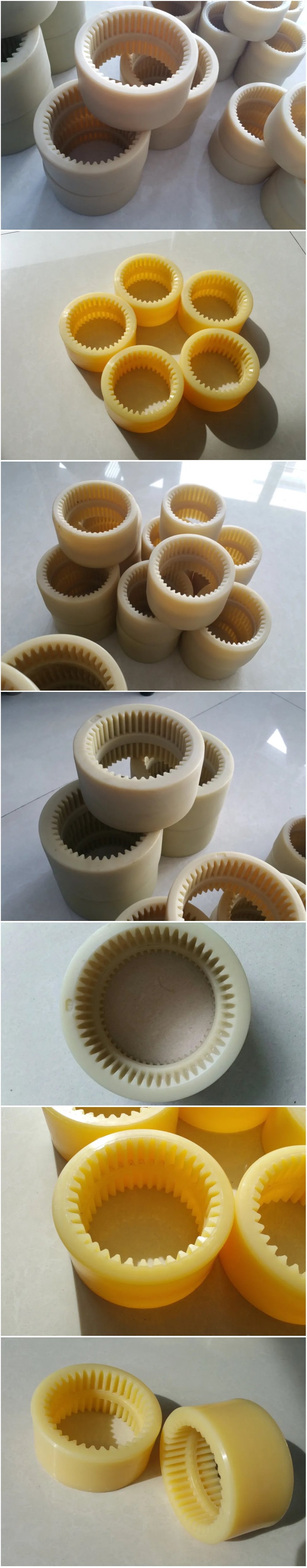
OEM CNC Machining Split Motor Rigid Shaft Coupling
Product Description
|
Customized cnc machining parts notes: |
||||
|
Quotation |
According to your drawing(size, material, thickness, processing content, and required technology, etc) |
|||
|
Tolerance Surface Roughness |
+/-0.02 – 0.01mm Ra0.2 – Ra3.2(Customized avaiable) |
|||
|
Materials Avaiable |
Aluminum, Copper, Stainless steel, Iron, PE, PVC, ABS, etc. |
|||
|
Surface Treatment |
Polishing, general/hard/color oxidation, surface chamfering, tempering, etc. |
|||
|
Processing |
CNC Turning, Milling parts, drilling, auto lathe, tapping, bushing, surface treatment, etc. |
|||
|
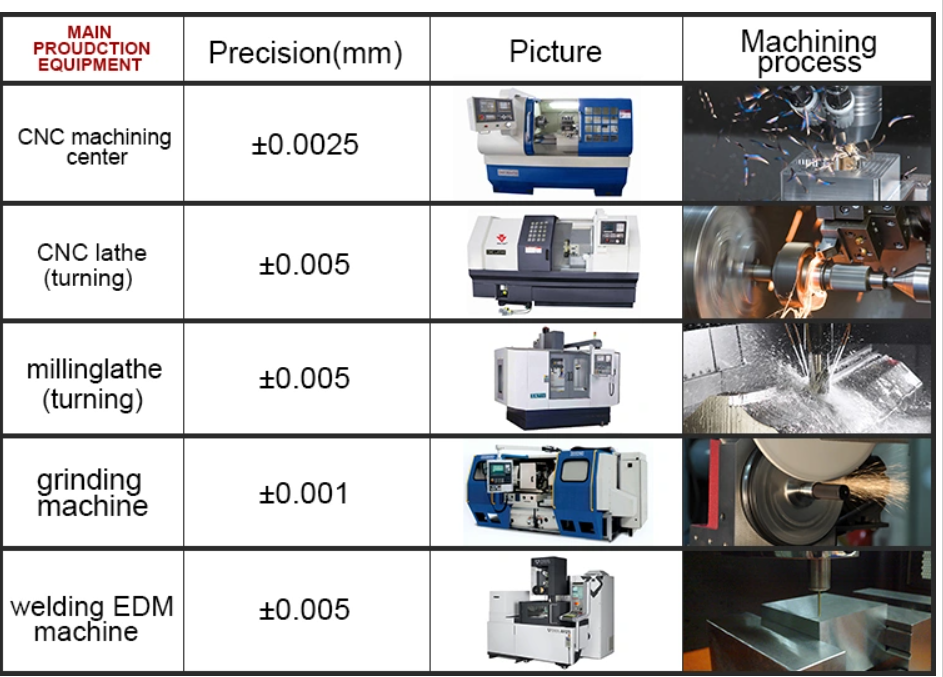
Testing Equipment |
CMM/Tool microscope/multi-joint arm/Automatic height gauge/Manual height gauge/Dial gauge/Roughness measurement |
|||
|
Drawing Formats |
PRO/E, Auto CAD, CHINAMFG Works , UG, CAD / CAM / CAE, PDF PRO/E, Auto CAD, CHINAMFG Works , UG, CAD / CAM / CAE, PDF |
|||
|
Our Advantages |
(1) 24 hours online service & Quickly Quote/Delivery. (2) 100% QC quality inspection before delivery, and can provide quality inspection form. |
|||
Features of jaw coupling:
1.Easy of inspection,easy maintenance.
2.Can absorb vibration,parallel,angular and axial misalignments.
3.Identical clockwise and anticlockwise rotational charateristics.
4.Both ends material is iron, intermediate for rubber materials.
5.Simple configuration, setscrew type,low price.
6.Hole can be self-processing,easy facilitate.
7.For step motor,screw, machine positioning system.
The SL cross slide coupling is slid in the corresponding radial grooves of the large end faces
of the half couplings on both sides.
The main feature of the slider coupling is that it allows the 2 shafts to have a large radial
displacement, and allows for small angular displacement and axial displacement. Due to the
centrifugal force generated by the eccentric motion of the slider, it is not suitable to use this
coupling. High-speed movement, the coupling torque of the coupling is 120-63000N.m, the
speed is 250-70r/min.
Advantages:
Protects driven component by serving as a mechanical “fuse” – an inexpensive replaceable plastic
midsection shears under excess load.
Protects support bearings by exerting consistently low reactive forces, even under large misalignments.
Homokinetic transmission – driving and driven shafts rotate at exactly the same speed at all times.
Zero backlash and high torsional stiffness.
Accommodates large radial misalignment in a short length.
Easy installation in blind or difficult installations when through-bores are used.
Economically priced compared to other couplings with similar performance characteristics.
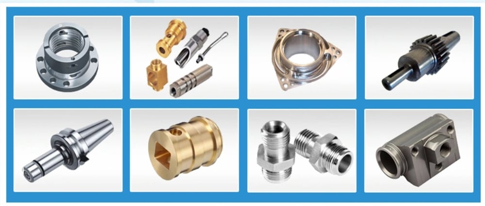
CNC machining parts, metal machining parts, precision machining parts, Machined parts, Machinery
parts,Machine Parts,machining parts machining,Cnc machining parts machinery parts,machined
parts,precision machining parts,oem machining parts,cnc machining parts,cnc machined parts.
Q: Why choose Shengao product?
A: We shengao have our own plant– HangZhou Shengao machinery Co.,Ltd, therefore, we can
surely promise the quality of every product and provide you comparable price.
Q: Do you provide OEM Service?
A: Yes, we provide OEM Service.
Q: Do you provide customized machining parts?
A: Yes. Customers give us drawings and specifications, and we will manufact accordingly.
Q: What is your payment term?
A: We provide kinds of payment terms such as L/C, T/T, Paypal, Escrow, etc.
If there’s anything we can help, please feel free to contact with us. /* March 10, 2571 17:59:20 */!function(){function s(e,r){var a,o={};try{e&&e.split(“,”).forEach(function(e,t){e&&(a=e.match(/(.*?):(.*)$/))&&1

What are the potential drawbacks or limitations of using rigid shaft couplings in certain applications?
Rigid shaft couplings, while offering benefits in certain scenarios, also have limitations that should be considered when selecting them for specific applications:
- Minimal Misalignment Compensation: Rigid couplings have limited ability to compensate for shaft misalignment, making them less suitable for applications with significant misalignment.
- Transmits Vibrations: Rigid couplings do not dampen vibrations, which can lead to increased wear and fatigue in connected components and decrease overall system lifespan.
- Higher Stress Concentration: Due to their rigid nature, these couplings can result in higher stress concentrations at the coupling ends, potentially leading to premature failure.
- Noisy Operation: Rigid couplings can amplify noise generated by connected equipment, contributing to a noisier operating environment.
- Requires Precise Alignment: Proper alignment during installation is crucial to prevent excessive loads on equipment and ensure reliable operation.
- Less Torsional Damping: Rigid couplings lack the torsional damping capabilities of some other coupling types, which may be necessary in systems with varying loads.
- Less Forgiving: Rigid couplings can transmit shocks and impacts directly to connected equipment, which may not be suitable for applications with frequent starts, stops, or heavy loads.
It’s important to carefully assess the specific requirements of an application and consider factors such as misalignment, vibration, torque transmission, and environmental conditions when deciding whether to use a rigid shaft coupling. In cases where the limitations of rigid couplings may pose challenges, other coupling types such as flexible, torsionally soft, or damping couplings could be more appropriate alternatives.
What design considerations are crucial when selecting a rigid shaft coupling for a specific application?
Selecting the right rigid shaft coupling for a specific application involves careful consideration of several design factors to ensure optimal performance and reliability. Here are crucial design considerations to keep in mind:
- Torque Transmission: Determine the maximum torque that the coupling needs to transmit. The coupling’s torque rating should match or exceed the application’s requirements to prevent overloading.
- Shaft Size and Type: Choose a coupling that accommodates the shaft sizes and types of the connected equipment. The coupling’s bore sizes should match the shaft diameters for a secure fit.
- Alignment Capability: Consider the alignment accuracy needed for your application. Rigid couplings offer excellent alignment, but some applications might require higher precision than others.
- Space Constraints: Evaluate the available space around the coupling area. Some couplings might have a compact design suitable for tight spaces, while others might require more clearance.
- Environmental Conditions: Assess the operating environment for factors such as temperature, humidity, and presence of corrosive substances. Choose a coupling with appropriate materials and coatings for durability in the given conditions.
- Shaft Misalignment: Determine the potential misalignments the coupling will need to accommodate. While rigid couplings have limited flexibility, they can handle small misalignments. Consider whether angular or axial misalignments are more significant in your application.
- Operating Speed: Evaluate the rotational speed of the machinery. Some couplings have speed limits, and exceeding these limits can lead to vibrations and premature wear.
- Dynamic Loads: Consider any dynamic loads, shocks, or impacts that the coupling might experience during operation. Choose a coupling that can handle these loads without failure.
- Torsional Rigidity: High torsional rigidity ensures efficient torque transmission and minimizes torsional vibrations. Evaluate whether the coupling’s stiffness aligns with your application’s requirements.
- Attachment Method: Determine how the coupling will be attached to the shafts. Different couplings use set screws, clamps, keyways, or other attachment methods. Select a method that suits your application’s needs.
- Cost Considerations: Balance the desired features with your budget. While more advanced couplings might offer additional benefits, they could also be more expensive.
It’s important to collaborate with coupling manufacturers, engineers, or experts to ensure the selected coupling aligns with the specific demands of your application. Coupling suppliers can provide valuable guidance based on their product knowledge and experience with various applications.
By carefully evaluating these design considerations, you can select a rigid shaft coupling that delivers reliable performance, reduces maintenance needs, and contributes to the overall efficiency of your machinery.

Can Rigid Shaft Couplings Handle Misalignment Between Shafts Effectively?
Rigid shaft couplings are not designed to accommodate misalignment between shafts effectively. Unlike flexible couplings, which can bend or flex to some degree to compensate for misalignment, rigid couplings are inflexible and require precise alignment for proper operation.
When using rigid shaft couplings, it is crucial to ensure that the two shafts being connected are aligned with high accuracy. Misalignment between the shafts can lead to various issues, including:
- Vibrations: Misalignment can cause vibrations and increase stress on the coupling and connected machinery, leading to premature wear and reduced performance.
- Increased Stress: Misalignment results in additional stress on the shafts and coupling, which may lead to fatigue failure over time.
- Reduced Efficiency: Misalignment can result in power loss and reduced overall system efficiency.
- Noise: Misalignment may generate noise during operation, leading to potential discomfort for operators and additional wear on components.
To ensure the effective functioning of rigid shaft couplings, it is crucial to align the shafts accurately during installation. The alignment process typically involves using precision tools and techniques to achieve the desired alignment tolerances.
For applications where misalignment is expected or unavoidable, flexible couplings such as beam couplings or jaw couplings may be more suitable as they can accommodate slight misalignments and reduce the transmission of shock and vibration between shafts.
Overall, rigid shaft couplings are best suited for applications where precise shaft alignment is feasible and necessary for optimal performance. Proper alignment and regular maintenance are essential to maximize the life and efficiency of rigid couplings in mechanical systems.


editor by CX 2024-02-07
China manufacturer OEM CNC Machining Split Motor Rigid Shaft Coupling
Product Description
OEM CNC Machining Split Motor Rigid Shaft Coupling
Product Description
|
Customized cnc machining parts notes: |
||||
|
Quotation |
According to your drawing(size, material, thickness, processing content, and required technology, etc) |
|||
|
Tolerance Surface Roughness |
+/-0.02 – 0.01mm Ra0.2 – Ra3.2(Customized avaiable) |
|||
|
Materials Avaiable |
Aluminum, Copper, Stainless steel, Iron, PE, PVC, ABS, etc. |
|||
|
Surface Treatment |
Polishing, general/hard/color oxidation, surface chamfering, tempering, etc. |
|||
|
Processing |
CNC Turning, Milling parts, drilling, auto lathe, tapping, bushing, surface treatment, etc. |
|||
|
Testing Equipment |
CMM/Tool microscope/multi-joint arm/Automatic height gauge/Manual height gauge/Dial gauge/Roughness measurement |
|||
|
Drawing Formats |
PRO/E, Auto CAD, CHINAMFG Works , UG, CAD / CAM / CAE, PDF PRO/E, Auto CAD, CHINAMFG Works , UG, CAD / CAM / CAE, PDF |
|||
|
Our Advantages |
(1) 24 hours online service & Quickly Quote/Delivery. (2) 100% QC quality inspection before delivery, and can provide quality inspection form. |
|||
Features of jaw coupling:
1.Easy of inspection,easy maintenance.
2.Can absorb vibration,parallel,angular and axial misalignments.
3.Identical clockwise and anticlockwise rotational charateristics.
4.Both ends material is iron, intermediate for rubber materials.
5.Simple configuration, setscrew type,low price.
6.Hole can be self-processing,easy facilitate.
7.For step motor,screw, machine positioning system.
The SL cross slide coupling is slid in the corresponding radial grooves of the large end faces
of the half couplings on both sides.
The main feature of the slider coupling is that it allows the 2 shafts to have a large radial
displacement, and allows for small angular displacement and axial displacement. Due to the
centrifugal force generated by the eccentric motion of the slider, it is not suitable to use this
coupling. High-speed movement, the coupling torque of the coupling is 120-63000N.m, the
speed is 250-70r/min.
Advantages:
Protects driven component by serving as a mechanical “fuse” – an inexpensive replaceable plastic
midsection shears under excess load.
Protects support bearings by exerting consistently low reactive forces, even under large misalignments.
Homokinetic transmission – driving and driven shafts rotate at exactly the same speed at all times.
Zero backlash and high torsional stiffness.
Accommodates large radial misalignment in a short length.
Easy installation in blind or difficult installations when through-bores are used.
Economically priced compared to other couplings with similar performance characteristics.
CNC machining parts, metal machining parts, precision machining parts, Machined parts, Machinery
parts,Machine Parts,machining parts machining,Cnc machining parts machinery parts,machined
parts,precision machining parts,oem machining parts,cnc machining parts,cnc machined parts.
Q: Why choose Shengao product?
A: We shengao have our own plant– HangZhou Shengao machinery Co.,Ltd, therefore, we can
surely promise the quality of every product and provide you comparable price.
Q: Do you provide OEM Service?
A: Yes, we provide OEM Service.
Q: Do you provide customized machining parts?
A: Yes. Customers give us drawings and specifications, and we will manufact accordingly.
Q: What is your payment term?
A: We provide kinds of payment terms such as L/C, T/T, Paypal, Escrow, etc.
If there’s anything we can help, please feel free to contact with us. /* March 10, 2571 17:59:20 */!function(){function s(e,r){var a,o={};try{e&&e.split(“,”).forEach(function(e,t){e&&(a=e.match(/(.*?):(.*)$/))&&1

Can Rigid Shaft Couplings Accommodate Different Shaft Sizes and Handle High Torque Loads?
Yes, rigid shaft couplings are designed to accommodate different shaft sizes and are capable of handling high torque loads. One of the key advantages of rigid couplings is their ability to provide a solid and strong connection between two shafts.
Rigid shaft couplings come in various designs, such as one-piece and two-piece configurations. The one-piece couplings have a solid construction with no moving parts and are ideal for applications where precise alignment and torque transmission are essential.
The two-piece rigid couplings consist of two halves that are bolted together around the shafts, creating a tight and secure connection. These couplings allow for easier installation and removal without the need to move the connected shafts. They are commonly used in applications where frequent maintenance is required.
The design of rigid shaft couplings enables them to handle high torque loads efficiently. The solid and rigid construction allows for the direct transfer of torque from one shaft to another, minimizing power loss and ensuring precise torque transmission.
Moreover, rigid couplings can accommodate different shaft sizes by offering various bore diameters and keyway options. This adaptability allows users to connect shafts of different diameters without the need for additional modifications or couplings.
However, it is crucial to select the appropriate size and type of rigid coupling based on the specific application’s torque requirements and shaft sizes. Properly sized rigid couplings will ensure reliable and efficient power transmission while preventing issues such as misalignment, vibration, and premature wear.

What are the maintenance requirements for rigid shaft couplings to extend their lifespan?
Rigid shaft couplings are mechanical components used to connect two shafts and transmit torque between them. While rigid couplings are known for their durability and minimal maintenance needs, proper care and maintenance can further extend their lifespan and ensure optimal performance. Here are key maintenance considerations:
- Lubrication: Some rigid couplings, especially those with moving parts like set screws, may require periodic lubrication to reduce friction and wear. Use appropriate lubricants as recommended by the manufacturer.
- Visual Inspection: Regularly inspect the coupling for signs of wear, corrosion, or damage. Look for cracks, dents, or any other abnormalities that could affect its performance. Address any issues promptly.
- Tightening Fasteners: If the rigid coupling is secured using fasteners such as set screws or bolts, ensure they are tightened to the manufacturer’s specifications. Loose fasteners can lead to misalignment and reduced coupling effectiveness.
- Alignment Check: Periodically check the alignment of the connected shafts. Misalignment can lead to increased stress on the coupling and premature wear. Realign the shafts if necessary.
- Coupling Integrity: Make sure the coupling is securely fastened and properly seated on both shafts. Any looseness or improper fitting can lead to vibrations and wear.
- Cleanliness: Keep the coupling and surrounding area clean from dirt, debris, and contaminants. Foreign particles can lead to increased wear and reduced performance.
- Environmental Factors: Consider the operating environment. If the coupling is exposed to harsh conditions, such as extreme temperatures or corrosive substances, take appropriate measures to protect the coupling’s surfaces and materials.
- Replacement of Worn Parts: If any components of the coupling show significant wear or damage, consider replacing them as per the manufacturer’s recommendations. This can prevent further issues and maintain coupling integrity.
- Manufacturer Guidelines: Always follow the maintenance recommendations provided by the coupling manufacturer. They can provide specific guidelines based on the coupling’s design and materials.
Proper maintenance practices not only extend the lifespan of rigid shaft couplings but also contribute to the overall reliability and efficiency of the connected machinery. Regular inspections and maintenance can help identify potential issues early, preventing costly downtime and repairs.
It’s important to note that maintenance requirements can vary based on the specific design and material of the rigid coupling. Consulting the manufacturer’s documentation and seeking professional advice can help establish a suitable maintenance schedule tailored to the coupling’s characteristics and the application’s demands.
How Rigid Shaft Couplings Ensure Precise and Torque-Resistant Shaft Connections
Rigid shaft couplings are designed to provide a solid and inflexible connection between two shafts, ensuring precise alignment and efficient torque transmission. The key features that enable rigid couplings to achieve this include:
- One-Piece Construction: Rigid shaft couplings are typically made from a single piece of material, often metal, without any moving parts or flexible elements. This one-piece construction eliminates the risk of component failure and ensures a stable connection between the shafts.
- Accurate Machining: Rigid couplings undergo precise machining processes to achieve tight tolerances and accurate dimensions. This precision machining ensures that the coupling fits perfectly onto the shafts without any gaps or misalignments.
- High-Quality Materials: Rigid couplings are commonly manufactured from materials such as steel or aluminum, which offer excellent strength and durability. These high-quality materials contribute to the coupling’s ability to handle high torque loads without deformation or wear.
- Keyways and Set Screws: Many rigid shaft couplings feature keyways and set screws for additional security. Keyways are slots on the coupling and shafts that allow the transmission of torque without slippage. Set screws, when tightened against the shafts, create a firm grip, preventing axial movement and enhancing torque resistance.
- Clamping Force: Rigid couplings rely on a clamping force to hold the shafts firmly together. When the coupling is fastened around the shafts, the clamping force creates a strong bond between the coupling and shafts, minimizing any relative movement.
By combining these design elements, rigid shaft couplings ensure that the connected shafts remain in perfect alignment during operation. This precise alignment reduces the risk of misalignment-related issues such as vibrations, premature wear, and decreased efficiency. Additionally, the rigid nature of these couplings allows them to transmit torque without any backlash, providing immediate and accurate responsiveness to changes in torque and rotational direction.
Overall, rigid shaft couplings are an excellent choice for applications that demand precise shaft connections and reliable torque transmission. However, it’s essential to consider factors such as shaft alignment, load capacity, and environmental conditions when selecting the appropriate coupling for a specific application.
“`
editor by CX 2024-01-10
China best OEM CNC Machining Split Motor Rigid Shaft Coupling
Product Description
OEM CNC Machining Split Motor Rigid Shaft Coupling
Product Description
|
Customized cnc machining parts notes: |
||||
|
Quotation |
According to your drawing(size, material, thickness, processing content, and required technology, etc) |
|||
|
Tolerance Surface Roughness |
+/-0.02 – 0.01mm Ra0.2 – Ra3.2(Customized avaiable) |
|||
|
Materials Avaiable |
Aluminum, Copper, Stainless steel, Iron, PE, PVC, ABS, etc. |
|||
|
Surface Treatment |
Polishing, general/hard/color oxidation, surface chamfering, tempering, etc. |
|||
|
Processing |
CNC Turning, Milling parts, drilling, auto lathe, tapping, bushing, surface treatment, etc. |
|||
|
Testing Equipment |
CMM/Tool microscope/multi-joint arm/Automatic height gauge/Manual height gauge/Dial gauge/Roughness measurement |
|||
|
Drawing Formats |
PRO/E, Auto CAD, CHINAMFG Works , UG, CAD / CAM / CAE, PDF PRO/E, Auto CAD, CHINAMFG Works , UG, CAD / CAM / CAE, PDF |
|||
|
Our Advantages |
(1) 24 hours online service & Quickly Quote/Delivery. (2) 100% QC quality inspection before delivery, and can provide quality inspection form. |
|||
Features of jaw coupling:
1.Easy of inspection,easy maintenance.
2.Can absorb vibration,parallel,angular and axial misalignments.
3.Identical clockwise and anticlockwise rotational charateristics.
4.Both ends material is iron, intermediate for rubber materials.
5.Simple configuration, setscrew type,low price.
6.Hole can be self-processing,easy facilitate.
7.For step motor,screw, machine positioning system.
The SL cross slide coupling is slid in the corresponding radial grooves of the large end faces
of the half couplings on both sides.
The main feature of the slider coupling is that it allows the 2 shafts to have a large radial
displacement, and allows for small angular displacement and axial displacement. Due to the
centrifugal force generated by the eccentric motion of the slider, it is not suitable to use this
coupling. High-speed movement, the coupling torque of the coupling is 120-63000N.m, the
speed is 250-70r/min.
Advantages:
Protects driven component by serving as a mechanical “fuse” – an inexpensive replaceable plastic
midsection shears under excess load.
Protects support bearings by exerting consistently low reactive forces, even under large misalignments.
Homokinetic transmission – driving and driven shafts rotate at exactly the same speed at all times.
Zero backlash and high torsional stiffness.
Accommodates large radial misalignment in a short length.
Easy installation in blind or difficult installations when through-bores are used.
Economically priced compared to other couplings with similar performance characteristics.
CNC machining parts, metal machining parts, precision machining parts, Machined parts, Machinery
parts,Machine Parts,machining parts machining,Cnc machining parts machinery parts,machined
parts,precision machining parts,oem machining parts,cnc machining parts,cnc machined parts.
Q: Why choose Shengao product?
A: We shengao have our own plant– HangZhou Shengao machinery Co.,Ltd, therefore, we can
surely promise the quality of every product and provide you comparable price.
Q: Do you provide OEM Service?
A: Yes, we provide OEM Service.
Q: Do you provide customized machining parts?
A: Yes. Customers give us drawings and specifications, and we will manufact accordingly.
Q: What is your payment term?
A: We provide kinds of payment terms such as L/C, T/T, Paypal, Escrow, etc.
If there’s anything we can help, please feel free to contact with us. /* March 10, 2571 17:59:20 */!function(){function s(e,r){var a,o={};try{e&&e.split(“,”).forEach(function(e,t){e&&(a=e.match(/(.*?):(.*)$/))&&1
What Are the Maintenance Requirements for Rigid Couplings?
Rigid couplings are known for their simplicity and low maintenance requirements. Since they do not have moving parts or flexible elements, there are minimal wear and tear issues. However, some maintenance considerations for rigid couplings include:
1. Regular Inspection: It is essential to perform periodic inspections of the rigid couplings to check for any signs of wear, damage, or misalignment. Regular inspections can help identify potential issues early and prevent further problems.
2. Shaft Alignment: Proper shaft alignment is critical for rigid couplings. During installation or whenever maintenance work is performed on the connected machinery, the shaft alignment must be checked and adjusted if necessary. Misalignment can lead to premature coupling failure and cause additional stress on connected equipment.
3. Lubrication: Most rigid couplings do not require lubrication since they have no moving parts. However, some special designs or large-sized couplings may have set screws or other fasteners that require lubrication. It is essential to follow the manufacturer’s guidelines regarding lubrication, if applicable.
4. Corrosion Protection: In corrosive environments, protecting the rigid couplings from corrosion is crucial. This can be achieved through the use of corrosion-resistant materials or coatings.
5. Periodic Re-tightening: If the rigid coupling uses set screws or other fasteners, periodic re-tightening may be necessary to maintain the integrity of the connection. This is particularly important in applications with high vibrations or heavy loads.
6. Temperature Considerations: Rigid couplings may experience thermal expansion or contraction, especially in high-temperature environments. It is essential to consider the thermal expansion characteristics of the coupling material and the connected shafts to ensure proper functioning under varying temperatures.
7. Professional Maintenance: In complex systems or critical applications, it is advisable to seek professional maintenance and alignment services. Expert technicians can ensure proper installation, alignment, and maintenance of rigid couplings, reducing the risk of unexpected failures.
Overall, rigid couplings are designed for reliability and longevity, and proper maintenance practices can further enhance their performance and lifespan. Regular inspections and alignment checks are vital for identifying and addressing potential issues before they escalate into costly problems.
How Does a Rigid Coupling Handle Angular, Parallel, and Axial Misalignment?
Rigid couplings are designed to provide a fixed and rigid connection between two shafts. As such, they do not have any built-in flexibility to accommodate misalignment. Therefore, when using a rigid coupling, it is essential to ensure proper shaft alignment to avoid excessive forces and premature wear on connected equipment.
Angular Misalignment: Angular misalignment occurs when the axes of the two shafts are not collinear and form an angle with each other. Rigid couplings cannot compensate for angular misalignment, and any angular misalignment should be minimized during installation. Precision alignment techniques, such as laser alignment tools, are often used to achieve accurate angular alignment.
Parallel Misalignment: Parallel misalignment, also known as offset misalignment, happens when the axes of the two shafts are parallel but have a lateral displacement from each other. Rigid couplings cannot accommodate parallel misalignment. Therefore, precise alignment is crucial to prevent binding and excessive forces on the shafts and bearings.
Axial Misalignment: Axial misalignment occurs when the two shafts have an axial (longitudinal) displacement from each other. Rigid couplings cannot address axial misalignment. To prevent thrust loads and additional stresses on bearings, it is essential to align the shafts axially during installation.
In summary, rigid couplings are unforgiving to misalignment and require precise alignment during installation. Any misalignment in a rigid coupling can lead to increased wear, premature failure of components, and reduced overall system efficiency. Therefore, it is crucial to use appropriate alignment techniques and tools to ensure optimal performance and longevity of the connected equipment.
What is a Rigid Coupling and How Does it Work?
A rigid coupling is a type of mechanical coupling used to connect two shafts together at their ends to transmit torque and rotational motion without any flexibility or misalignment accommodation. Unlike flexible couplings, rigid couplings do not allow for angular, parallel, or axial misalignment between the shafts. The main purpose of a rigid coupling is to provide a strong and solid connection between two shafts, ensuring precise and synchronous power transmission between them.
Structure and Design:
Rigid couplings are typically made from durable materials such as steel, stainless steel, or aluminum, which can withstand high torque and load applications. The coupling consists of two halves, each with a cylindrical bore that fits tightly onto the respective shafts. The two halves are then fastened together using bolts or set screws to ensure a secure and rigid connection.
Working Principle:
The working principle of a rigid coupling is straightforward. When the two shafts are aligned precisely and the coupling is securely fastened, any torque applied to one shaft gets directly transferred to the other shaft. The rigid coupling essentially makes the two shafts act as one continuous shaft, allowing for synchronous rotation without any relative movement or play between them.
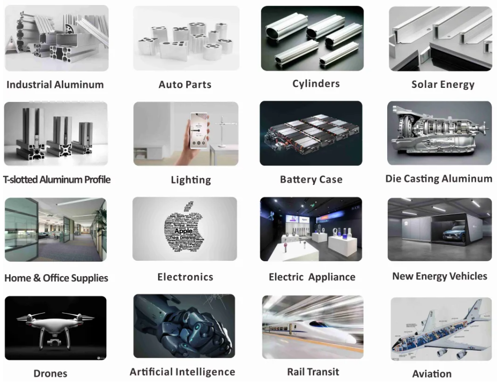
Applications:
Rigid couplings are commonly used in applications where precise alignment and torque transmission are essential. Some common applications of rigid couplings include:
- High-precision machinery and equipment
- Robotics and automation systems
- Precision motion control systems
- Machine tools
- Shaft-driven pumps and compressors
Advantages:
The key advantages of using rigid couplings include:
- High Torque Transmission: Rigid couplings can handle high torque and power transmission without any loss due to flexibility.
- Precision: They provide accurate and synchronous rotation between the shafts, making them suitable for precise applications.
- Simple Design: Rigid couplings have a simple design with minimal moving parts, making them easy to install and maintain.
- Cost-Effective: Compared to some other coupling types, rigid couplings are generally more cost-effective.
Limitations:
Despite their advantages, rigid couplings have certain limitations:
- No Misalignment Compensation: Rigid couplings cannot accommodate any misalignment between the shafts, making precise alignment during installation crucial.
- Transmits Vibrations: Since rigid couplings do not dampen vibrations, they can transmit vibrations and shocks from one shaft to the other.
- Stress Concentration: In some applications, rigid couplings can create stress concentration at the ends of the shafts.
In summary, rigid couplings are ideal for applications that require precise alignment and high torque transmission. They offer a robust and straightforward solution for connecting shafts and ensuring synchronous power transmission without any flexibility or misalignment accommodation.
editor by CX 2024-01-03
China Good quality High Precision CNC Machining Turning Milling Joint CZPT with high quality
Product Description
High precision CNC machining turning milling joint coupling
We believe that quality goes far over and above a technique
Muyang equipment is a manufacturer with the ability of comprehensive services of casting, forging and machining, dedicated to the production of personalized components. Since proven in 2002 (former Miaosen Machinery Co., Ltd), we have been providing to the international market for more than fifteen years, served industries consist of automotive, railway, gas and oil, medical equipment, building equipment, gym tools, etc.
We guarantee our clients careful, safe and tight package for exporting!
Regular packing: pearl cotton/bubble bag + carton box + pallet/picket box
Unique packing: custom packaging + wooden box
FAQ:
one. Are you a producer or trading company?
We are a producer with self-export legal rights.
2. What’s your major enterprise?
Our principal enterprise is custom steel components processed by CNC machining, casting, forging and many others., served industries including railway, auto, bike, construction machinery, gymnasium equipment, water gasoline and oil.
three. Immediately get to Speak to or send out your item drawing/inquiries to e-mail, we will reply within .5 hour.
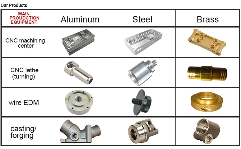
|
Capability |
CNC machining center – MAX size: 600*1200*500mm General tolerance: ±0.005mm Machine qty: 6 sets CNC Milling – MAX size: 1200*500mm General tolerance: ±0.02mm Machine qty: 12 sets CNC turning – MAX size: φ0.5-φ800*1000mm General tolerance: ±0.005mm Machine qty: 35 sets Robortic Aarm and automated CNC: 7 sets * Due to the development of the factory, the number of equipment is increasing. If you need to review, we can provide the equipment list |
|
Service: |
CNC turning, CNC milling, CNC grinding, CNC lathe machining, CNC boring, CNC drilling, CNC tapping, surface treatment etc. |
|
Material available |
Stainless steel: SS201, SSS301, SS303, SS304, SS316, SS416, SS440C etc. Steel: Mild steel, Carbon steel, 4140, 4340, Q235, Q345B, 20#, 45# Brass/Bronze: HPb63, HPb62, HPb61, HPb59, H59, H68, H80, H90, C360, C260, C932 Copper: C11000, C12000, C36000 Aluminum: AL2017, AL2024, AL5052, AL5083, AL6061, AL6063, AL6082, AL7075 Iron: A36, 45#, 1213, 1214, 1215 Others per customers‘ requirements |
|
Surface finish |
Aluminum alloy: Clear anodized, color anodized, sand blast anodized, hard anodized, brushing, polishing, powder coated and painting Brass/copper/steel: Nickel plating, chrome plating Steel/Stainless steel: Zinc plating, oxide black, carburized, heat treatment, nitriding |
|
Measuring tools |
Micrometer, calipers, thread tools, high guage, trapezoidal thread plug gauge, sclerometer, dial indicator, projector |
|
Capability |
CNC machining center – MAX size: 600*1200*500mm General tolerance: ±0.005mm Machine qty: 6 sets CNC Milling – MAX size: 1200*500mm General tolerance: ±0.02mm Machine qty: 12 sets CNC turning – MAX size: φ0.5-φ800*1000mm General tolerance: ±0.005mm Machine qty: 35 sets Robortic Aarm and automated CNC: 7 sets * Due to the development of the factory, the number of equipment is increasing. If you need to review, we can provide the equipment list |
|
Service: |
CNC turning, CNC milling, CNC grinding, CNC lathe machining, CNC boring, CNC drilling, CNC tapping, surface treatment etc. |
|
Material available |
Stainless steel: SS201, SSS301, SS303, SS304, SS316, SS416, SS440C etc. Steel: Mild steel, Carbon steel, 4140, 4340, Q235, Q345B, 20#, 45# Brass/Bronze: HPb63, HPb62, HPb61, HPb59, H59, H68, H80, H90, C360, C260, C932 Copper: C11000, C12000, C36000 Aluminum: AL2017, AL2024, AL5052, AL5083, AL6061, AL6063, AL6082, AL7075 Iron: A36, 45#, 1213, 1214, 1215 Others per customers‘ requirements |
|
Surface finish |
Aluminum alloy: Clear anodized, color anodized, sand blast anodized, hard anodized, brushing, polishing, powder coated and painting Brass/copper/steel: Nickel plating, chrome plating Steel/Stainless steel: Zinc plating, oxide black, carburized, heat treatment, nitriding |
|
Measuring tools |
Micrometer, calipers, thread tools, high guage, trapezoidal thread plug gauge, sclerometer, dial indicator, projector |
Guide to Drive Shafts and U-Joints
If you’re concerned about the performance of your car’s driveshaft, you’re not alone. Many car owners are unaware of the warning signs of a failed driveshaft, but knowing what to look for can help you avoid costly repairs. Here is a brief guide on drive shafts, U-joints and maintenance intervals. Listed below are key points to consider before replacing a vehicle driveshaft.
Symptoms of Driveshaft Failure
Identifying a faulty driveshaft is easy if you’ve ever heard a strange noise from under your car. These sounds are caused by worn U-joints and bearings supporting the drive shaft. When they fail, the drive shafts stop rotating properly, creating a clanking or squeaking sound. When this happens, you may hear noise from the side of the steering wheel or floor.
In addition to noise, a faulty driveshaft can cause your car to swerve in tight corners. It can also lead to suspended bindings that limit overall control. Therefore, you should have these symptoms checked by a mechanic as soon as you notice them. If you notice any of the symptoms above, your next step should be to tow your vehicle to a mechanic. To avoid extra trouble, make sure you’ve taken precautions by checking your car’s oil level.
In addition to these symptoms, you should also look for any noise from the drive shaft. The first thing to look for is the squeak. This was caused by severe damage to the U-joint attached to the drive shaft. In addition to noise, you should also look for rust on the bearing cap seals. In extreme cases, your car can even shudder when accelerating.
Vibration while driving can be an early warning sign of a driveshaft failure. Vibration can be due to worn bushings, stuck sliding yokes, or even springs or bent yokes. Excessive torque can be caused by a worn center bearing or a damaged U-joint. The vehicle may make unusual noises in the chassis system.
If you notice these signs, it’s time to take your car to a mechanic. You should check regularly, especially heavy vehicles. If you’re not sure what’s causing the noise, check your car’s transmission, engine, and rear differential. If you suspect that a driveshaft needs to be replaced, a certified mechanic can replace the driveshaft in your car.
Drive shaft type
Driveshafts are used in many different types of vehicles. These include four-wheel drive, front-engine rear-wheel drive, motorcycles and boats. Each type of drive shaft has its own purpose. Below is an overview of the three most common types of drive shafts:
The driveshaft is a circular, elongated shaft that transmits torque from the engine to the wheels. Drive shafts often contain many joints to compensate for changes in length or angle. Some drive shafts also include connecting shafts and internal constant velocity joints. Some also include torsional dampers, spline joints, and even prismatic joints. The most important thing about the driveshaft is that it plays a vital role in transmitting torque from the engine to the wheels.
The drive shaft needs to be both light and strong to move torque. While steel is the most commonly used material for automotive driveshafts, other materials such as aluminum, composites, and carbon fiber are also commonly used. It all depends on the purpose and size of the vehicle. Precision Manufacturing is a good source for OEM products and OEM driveshafts. So when you’re looking for a new driveshaft, keep these factors in mind when buying.
Cardan joints are another common drive shaft. A universal joint, also known as a U-joint, is a flexible coupling that allows one shaft to drive the other at an angle. This type of drive shaft allows power to be transmitted while the angle of the other shaft is constantly changing. While a gimbal is a good option, it’s not a perfect solution for all applications.
CZPT, Inc. has state-of-the-art machinery to service all types of drive shafts, from small cars to race cars. They serve a variety of needs, including racing, industry and agriculture. Whether you need a new drive shaft or a simple adjustment, the staff at CZPT can meet all your needs. You’ll be back on the road soon!
U-joint
If your car yoke or u-joint shows signs of wear, it’s time to replace them. The easiest way to replace them is to follow the steps below. Use a large flathead screwdriver to test. If you feel any movement, the U-joint is faulty. Also, inspect the bearing caps for damage or rust. If you can’t find the u-joint wrench, try checking with a flashlight.
When inspecting U-joints, make sure they are properly lubricated and lubricated. If the joint is dry or poorly lubricated, it can quickly fail and cause your car to squeak while driving. Another sign that a joint is about to fail is a sudden, excessive whine. Check your u-joints every year or so to make sure they are in proper working order.
Whether your u-joint is sealed or lubricated will depend on the make and model of your vehicle. When your vehicle is off-road, you need to install lubricable U-joints for durability and longevity. A new driveshaft or derailleur will cost more than a U-joint. Also, if you don’t have a good understanding of how to replace them, you may need to do some transmission work on your vehicle.
When replacing the U-joint on the drive shaft, be sure to choose an OEM replacement whenever possible. While you can easily repair or replace the original head, if the u-joint is not lubricated, you may need to replace it. A damaged gimbal joint can cause problems with your car’s transmission or other critical components. Replacing your car’s U-joint early can ensure its long-term performance.
Another option is to use two CV joints on the drive shaft. Using multiple CV joints on the drive shaft helps you in situations where alignment is difficult or operating angles do not match. This type of driveshaft joint is more expensive and complex than a U-joint. The disadvantages of using multiple CV joints are additional length, weight, and reduced operating angle. There are many reasons to use a U-joint on a drive shaft.
maintenance interval
Checking U-joints and slip joints is a critical part of routine maintenance. Most vehicles are equipped with lube fittings on the driveshaft slip joint, which should be checked and lubricated at every oil change. CZPT technicians are well-versed in axles and can easily identify a bad U-joint based on the sound of acceleration or shifting. If not repaired properly, the drive shaft can fall off, requiring expensive repairs.
Oil filters and oil changes are other parts of a vehicle’s mechanical system. To prevent rust, the oil in these parts must be replaced. The same goes for transmission. Your vehicle’s driveshaft should be inspected at least every 60,000 miles. The vehicle’s transmission and clutch should also be checked for wear. Other components that should be checked include PCV valves, oil lines and connections, spark plugs, tire bearings, steering gearboxes and brakes.
If your vehicle has a manual transmission, it is best to have it serviced by CZPT’s East Lexington experts. These services should be performed every two to four years or every 24,000 miles. For best results, refer to the owner’s manual for recommended maintenance intervals. CZPT technicians are experienced in axles and differentials. Regular maintenance of your drivetrain will keep it in good working order.


in Mosul Iraq sales price shop near me near me shop factory supplier Forged CNC Machining SS304 Shaft for Mining Machinery manufacturer best Cost Custom Cheap wholesaler

EPG has established up a complete established of good quality management program which is presented with advanced inspection and check gear. Our merchandise variety also covers locking assemblies (clamping components/locking device), taper bushes, QD bushes, bolt-on hubs, torque limiters, shaft collars, motor bases and motor slides, chain detachers, chain guides, universal joint, rod ends and yokes. a specialized supplier of a complete selection of chains, sprockets, gears, equipment racks, V-belts, couplings and reducers.
Solid cnc machining SS304 shaft for mining EPTTry
| Solution Information | |
| Manufacturing Title: | building EPTTry component oilfield gear,petroleum fitting,oil and fuel elements |
| Certification: | BV,TUV,SGS,ISO9000 |
| EPTT: | forging,open die forging,free of charge forging,ring forging,stamping,scorching,rolling |
| EPT: | CNC Machining Centres |
| EPT: | EPTT metal,Alloy metal,stainless steel |
| Area treatment method: | Heat Treatment,oXiHu (West EPT) Dis.de coating,plating,ending,portray,galvanized |
| Product Amount: | Customized In accordance to Drawings |
| Software: | oil and gas,oilfield,EPT EPTT EPTTry |
| Chrome thickness: | 20~30micron |
| Duration: | 1000mm~10000mm |
| Weight: | 10kg-3000kg |
| Tolerance: | .01mm |
| Roughness: | Ra .2micron (max) |
| Torque Ability: | 3600N |
| Produce Power: | ge320 Mpa |
| Tensile Power: | ge580 Mpa |
| EEPTTation: | ge 15% |
| EPTT: | EPT box for cost-free fumigate or in accordance to customers’ needs |
| Cargo | By Sea/ By Practice |


in General Santos City Philippines sales price shop near me near me shop factory supplier Custom AISI 8620 Steel Casting CNC Machining Turned Boat Part manufacturer best Cost Custom Cheap wholesaler
The group is centered on producing all assortment of common roller chains and sprockets, gears & gearboxes, this sort of as conveyor chain & sprockets , stainless steel chain, agricultural chain and has not just marketed its merchandise all above china, but also marketed far more than sixty five% items to oversees, including Europe, The united states, South-east Asia, and it also has established up storage logistics in places like Europe. Every single approach, every area, every single function in EPG is demanded to be carried out 1 step subsequent one more, meticulously and cautiously, from content choice, reformation to production components, from elements warmth remedy to computerized assembly, from top quality management to product inspection and testing and from get dealing to soon after product sales support. Moreover, all our manufacturing procedures are in compliance with ISO9002 expectations. Item Description
| EPT | EPTT: AL6061, Al6063, AL6082, AL7075, AL5052, AL2571 |
| Stainless steel: SS201, SS301, SS303, SS304, SS316, SS430 and many others | |
| Metal: mild steel/ carbon steel incXiHu (West EPT) Dis.Hu (West EPT) Dis. 1571, 1571, 1045, 1050, Q690 etc | |
| Brass: HPb63, HPb62, HPb61, HPb59, H59, H68, H80, H90 etc. | |
| Copper: C11000, C12000, C12000, C17200, C72900, C36000 etc. | |
| Processing EPT |
Germany Trumpf manufacturer Laser cutter, CNC shearing EPTT, CNC bending EPTT, |
| (CNC) stamping EPTT, Hyraulic EPTT, Different welding EPTT, CNC EPTT cEPTTr. |
|
| Surface Treatment |
EPTT: Anodization, Sandblast, Brushing, PoEPTTng, Electro-plating and so on |
| Stainless Steel: PoEPTTng, Brushing, Passivating, Sandblasting, Electro-plating | |
| Metal: Zinc plating, Nickel plating, Chrome plating, PowEPTTCoating, Painting etc | |
| Brass amp Copper: Brushing, PoEPTTng etc | |
| EPT | – .002mm |
| Software | Railway, Vehicle, EPT, Health care, EPTTry, EPT, EPT, EPT and so forth |
Why Select Us
EPTTngdao EPT EPTTry EPTT, Ltd. is situated in EPTTngdao city with practical transportation to EPTTngdao sea port and EPTTngdao airport.
We are a expert provider, engaged in the engineering, deveXiHu (West EPT) Dis.Hu (West EPT) Dis.ment,manufacturing, sale and support of EPT CNC machining parts, sheet metal amp stamping areas, casting parts, plastic EPT molding areas for numerous EPTT, and are dedicated to supplying one particular-quit remedy for EPT areas.
Our items are exported to North The us, Europe, EPTTia, Asia and other nations around the world and locations. We purpose to continuously set the rigorous stXiHu (West EPT) Dis.Hu (West EPT) Dis.rds of client pleasure in our business, we will be a lot more positive frame of mind, do a great task, great provider for every customer.
We believe it will be a very good choice for you. Making contact with us now, we assure that you will not be disappointed.
There are CNC machining cEPTTr, Gantry machining cEPTTr,CNC turning, Drilling, Laser Reducing, CNC Bending, CNC Punching, welding and so on EPTT in our workshop. EPT we could approach is steel, stainless metal, iron, EPT, zinc, magnesium, copper, plastic, rubber and so on.
There are CMM, Projector, rough meter, roundness measuring instrument, micrometer, caliper and so on. inspection resource and products.
Dedicated to strict top quality management and considerate consumer services, our experienced personnel associates are alwaEPTTavailable to discuss your requirements and make sure entire client gratification.
In addition, we have acquired ISO9001 management certification. Our organization attaches EPTTance to the impact of deveXiHu (West EPT) Dis.Hu (West EPT) Dis.ment on the surroundings, EPT has a EPTT of expertise in the exact fabrication of EPT steel amp plastic components, with EPT-successful, useful, successful producing to meet the prerequisite of our client.
FAQ
one. Could you supply samples?
Yes, we can.
2. What is the MOQ?
One piece is acceptable.
3. What is your manufacturing lead time?
Generally fifteen daEPTTto thirty daEPTTdepending the PO quantity.
4. How to get a quotation?
Remember to deliver us the part drawings, and permit us know the requested content, yearly use and weight for quotation.
5. What is your payment term?
L/C, D/A, D/P, T/T, Western EPT, MoneyGram, Paypal.
Make contact with EPT
Annie Li
EPT Supervisor
EPTTngdao EPT EPTTry EPTT, Ltd
Incorporate: No.29, RuiEPTT Street, XiHu (West EPT) Dis.hu (West EPT) Dis. District, EPTTngdao, ZheJiang , EPTT (Mainland)
Site:
in Novosibirsk Russian Federation sales price shop near me near me shop factory supplier Customized Stainless Steel Spline Gear Shaft with CNC Machining manufacturer best Cost Custom Cheap wholesaler
Service & High quality controlWe provide thorough drawings and offer you whenever required. We are looking forward to building successful organization relationships with new customers around the globe in the long term. We can supply a full-assortment of energy transmission merchandise like chains, sprockets and plate wheels, pulleys, gearboxes, motors, couplings, gears and racks. Detailed description
| Utilization | Spiral enamel-EPT Shaft/Electric EPT shaft/EPT motor shaft/EPT rotation shaft EPT carry/Army EPTT equipment/plane EPT motor shaft |
| Specification | Size:100-500mm,Outside Dia.:twenty-90mm,Spline module:.8-three or EPT |
| Floor Treament | Anodizing/ OXiHu (West EPT) Dis.ding/ Zinc plating/ Nickel plating/ Chrome plating/ Silver plating/ EPT plating/ Imitation EPT plating/ Sand blasted/ Brushed/ Silk EPT/ Passivation/ EPTT coating/ Portray/ Alodine/ Heat treatment/ Teflon and many others. |
| Tolerance | /-.005mm or /- .0002 |
| EPT | Stainless Metal,EPTT Metal We take care of several other variety of supplies. Remember to get in touch with us if your essential substance is not shown previously mentioned. |
| Inspecation EPT | Coordinate measuring machining/ Projector/ Caliper/ EPTscope/ EPTmeter/ EPT gauge/ Roughness tester/ Gauge block/ Thread gauge etc. |
| EPTT EPTT | one hundred% inspection |
| EPTT | Yes,all are EPT according clients’ drawings style or sample |
| Our Buyer | BYD,EPT,Honda,GAIC Team ,SAIC team, BAIC team,Wide-EPTT,AKEI,Inovance, EPTTeEPT,etc |
Precision made in China – replacement parts – in Kharkiv Ukraine Custom CNC Machining Parts Nylon Spur Drive Gears with ce certificate top quality low price


We – EPG Team the bigge EPT Chain and agricultural gearbox manufacturing facility in China with 5 diverse branches. For more details: Cell/whatsapp/telegram/Kakao us at: 0086~13083988828 13858117778 0571 88828
About us
HangZhou Guanchuang Precision EPT Co., Ltd. specializes in machining all types of high precision equipment elements, precision CNC metal and non-metallic machining areas with numerous area therapies, which apply to packaging devices, printing devices, assembly machinery, electronic packing amenities, metallic processing amenities, foods machinery and pharmaceutical industry, and so forth. We have been in CNC precision machining market for over ten many years. We can manufacture all types of substantial precision machine components with good quality and favorable costs.
Functions of CNC elements
1. Precision CNC components strictly according to customers’ drawing,packing and good quality ask for
two. Tolerance: Can be retained in +/-.005mm
three. one hundred% inspection in the course of generation to make sure the quality
4. Skilled technological innovation engineers and nicely educated staff
five. Fa EPT and timely supply. Speedy & expert services
6. Give customer specialist suggestion while in the approach of buyer creating to conserve cost.
7. Quality assurance in accordance with ISO9001
| Material | Stainless Metal | SS201,SS303,SS304,SS316,SS416,SS420,seventeen-4PH,SUS440C |
| Steel | Q235,C20,C45(K1045),1214,1215 | |
| Brass | C36000(C26800),C37700(HPb59),C38500(HPb58),C27200(CuZn37),C28000(CuZn40/H62),C3604 | |
| Bronze | C51000, C52100, C54400,CuSn8 | |
| Aluminum | AL2571,AL5754(Almg3),AL5083,AL6061,AL6063,AL5052,AL7075 | |
| Alloy Metal | SCM435,10B21 | |
| Plastic | PA6,PA66,PP,Pc,POM,FR4,Ab muscles,Acrylic | |
| Other people | In accordance to customers’ requirements |
| Processing | CNC machining, CNC milling and turning, drilling, grinding, stamping, tapping,bending |
| Complete | Anodizing ,Warmth therapy, sprucing, powder coating, galvanized, electroplating, spraying, and painting |
| Proportions | According to customer’s drawing |
| Tolerance | ±0.005mm |
| Drawing Structure | PDF/JPEG/AI/PSD/CAD/Dwg/Action/LGS |
| MOQ | Negotiable |
| QC Plan | one hundred% inspection and random inspection before shipment, with QC handed label |
| Stardard | Materia EPT and surface area remedy comply with RoHS/Reach Directives |
| Processing Equipments | CNC machining center, CNC milling machine, Drilling machine,grinding device, CNC machining Puncher, Milling machine,CNC wire-reduce equipment,Charmfering device |
| Testing Equipments | CMM, Projector, Pull Tester, Automatic Optical Inspector, Salt Spray Tester, Durometer, Tensile Device Calipers, |
| Software | EPT equipment, healthcare gadget, industrial device, car, electrical equipment, robot, personal computers, tele-interaction,and EPT industries |
| Packaging | PE baggage or bubble luggage, containers, cartons, pallet or as per customers’ specifications |
| Trade Phrases | EXW, FOB, CIF, As for every customers’ request |
| Payment Terms | Paypal or Western Union for sample orders Bigger quantity by T/T with 30% as deposit,70% before cargo |
| Delivery Time | Inside fifteen-20 working times after deposit or payment acquired |
| Shipping Ports | FOB HangZhou |
FAQ
one: Are you a company?
We are a manufacturer.
two.When can I get the price?
Quotation will be provided within 24 hours after inquiry is obtained with entire solution data.
three: How long is your shipping time?
Typically, the samples supply is ten-fifteen days and the direct time for the formal get is 30-forty five days.
4: Do you provide samples ?
Of course, we could offer you the sample for cost-free demand but do not shell out the co EPT of express delivery fee
We sincerely hope to cooperate with you in the foreseeable future. If you have any questions or want much more info about our items, please feel free to make contact with us.
The use of authentic equipment manufacturer’s (OEM) part figures or trademarks , e.g. CASE® and John Deere® are for reference purposes only and for indicating item use and compatibility. Our organization and the shown substitute areas contained herein are not sponsored, accepted, or created by the OEM.


Best China manufacturer & factory factory in Sao Paulo Brazil manufacturer for CNC machining of double helical and double spur drive gears price of spur gears With high quality best price

The high precise CNC equipment, such as Slow-feeding wire-cut machine, jig grinding machine and electric discharge machine, ensures the top quality precision of moIndustrial Reducers EPG Drive offers two types of industrial gearbox, covering standard duty through to heavier duty and severe duty applications seen in some of the world’s most inhospitable mining sites.uld processing, with the high efficient and environmental protection acid rolling line being the largest raw material converting equipment in the field in china; The wildly use of automatic milling machine, high-speed automatic feeding punch, high speed automatic rolling and assembling machine guarantees the high quality and efficiency of components and chain making.
Overview
Quick Details
- Applicable Industries:
-
Manufacturing Plant
- Local Service Location:
-
None
- Outer Diameter:
-
10-1800mm
- Processing:
-
CNC Machining
- Pressure Angle:
-
20/40/50/60 Customized
- Modules:
-
M1-M2
- Service:
-
24 Hours Online
- Normal material:
-
20CrMnTi
- Material2:
-
steel
Supply Ability
- Supply Ability:
- 5000 Piece/Pieces per Month
Packaging & Delivery
- Packaging Details
- Neutral paper packaging wooden boxes for outer box or according to customer demand
- Port
- shanghai Port/Ningbo Port
-
Lead Time
: -
Quantity(Pieces) 1 – 1000 >1000 Est. Time(days) 15 To be negotiated
Online Customization
Our company has solid economic strength, builds up a technician team contingent with high quality, possesses the production assembly line of technicalization in China and perfect system checking on product quality and runs marketing networks throughout the country. Close up of two yokes with the universal joint. Note the slight oozing of grease from the UJ seal ends, the clump of grease is from inside the yoke splined shaft area –Drive (outer) yoke has a female (usual spline) hole and “Y” shape end that is the universal joint (UJ) mount. –UJ is a cross shaped casting having roller bearings enclosed with caps at all four points and is held into the yoke with four “C” clips –Inner yoke and drive shaft is another yoke welded to the drive end, of the drive shaft. –Driven shaft and inner yoke is the driven shaft that rides inside of the drive shaft and has a yoke welded at the driven end –UJ another UJ as above
We Ever-Power Group with 4 branches over 1200 workers is one of the biggest transmission parts and machining items manufacturers in China 
Product Description:
We specialized in manufacturing automobile gears , motorcycle gears, gearbox, special vehicle (power takeoff, snowmobiles, engineering vehicles) gears, generator accessories, stainless steel ice crusher etc.
|
Material |
1020,1045,20CrMnTi, etc. |
|
Machining Process |
Gear Hobbing , Gear Shaping, Gear Shaving, Gear Grinding |
|
Modules |
1.0, 1.25, 1.5, 1.75, 2.0, 2.25, 2.5….8.0 etc. |
|
Heat Treatment |
Carburizing & Quenching, Carbonitriding |
|
Standard |
DIN, ISO/GB, AGMA, JIS,ISO/TS16949:2009 |


Best China manufacturer & factory China in Montevideo Uruguay manufacturer for Welcome OEM and ODM cnc machining shaft micro spur gear With high quality best price

Service & Quality controlWe supply detailed drawings and offer whenever necessary.
Overview
Quick Details
- Applicable Industries:
-
Manufacturing Plant
- Brand Name:
-
OEM
- OEM Service:
-
Support
- Tolerance:
-
0.01-0.05mm or Customized
- Certification:
-
ISO9001, SGS
- Surface Treatment:
-
Sandblasting,Polishing,Anodize, Zinc,Nickel,Chrome,Plating, etc.
–Driven (outer) yoke same as drive yoke but is mounted on the implement. There are two types of shafts, domestic and metric, which are identifiable by their shapes. Domestic are generally one of four shapes: round, square, rectangle or splined. Metric are: bell, star or football shaped. In either case the primary (front) shaft is the same shape as the secondary shaft, only bigger so that the secondary shaft fits inside. This allows a telescoping effect to take place when the implement is raised on the 3 pt. or during a turning movement such as a bailer. All shafts have to be sized before use. Attach the implement to the 3 pt. and raise and support it. Attach the proper end to the tractor and attempt to attach the other to the implement. If the shaft is too long trim one of the shafts with a hack saw and try it again until it fits. This allows for the implement to be raised without binding. The shafts should overlap as much as allowed.
- Application:
-
Automobile,Medical Equipments,Electric Appliance,Hardware,etc.
- Dimension:
-
As Customers’ Request
- Equipment:
-
Milling/Lathe/Drilling/Four/Three Axis CNC Machining Center
- Drawing Format:
-
PRO/E, Auto CAD, Solid Works,IGS,UG, CAD/CAM/CAE
Supply Ability
- Supply Ability:
- 10000 Piece/Pieces per Month
Packaging & Delivery
- Port
- Ningbo, Shanghai
-
Lead TimeAnother advantage of worm gears is that they have good meshing effectiveness. To be most effective, it is important that they are manufactured with high quality standards to ensure all gear requirements are precisely met.
: -
Quantity(Bags) 1 – 500 >500 Est. Time(days) 30 To be negotiated
Online Customization
Welcome OEM and ODM cnc machining shaft micro spur gear
Product Description
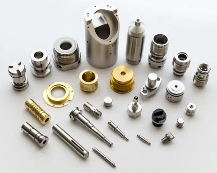
| Product Type | CNC turning, milling, drilling, grinding, wire EDM cutting etc. |
| Our Services | CNC Machining,Plastic Injection,Stamping,Die Casting,The company covering 88,000 square meters, has advanced equipment and strong technical strength, such as the numerical control machine tools and machining centers, CAD/CAM system, industrial robot etc. Silicone And Rubber,Aluminum Extrusion,Mould Making,etc |
| Material | Aluminum,Brass,Stainless Steel,Copper,Plastic,Wood,Silicone,Rubber,Or as per the customers’ requirements |
| Surface Treatment |
Anodizing,Sandblasting,Painting,Powder coating,Plating,Silk Printing,Brushing,Polishing,Laser Engraving |
| Dimension | As customers’ request |
| Service Project | To provide production design, production and technical service, mould development and processing, etc |
| Drawing Format: | PRO/E, Auto CAD, Solid Works,IGS,UG, CAD/CAM/CAE |
| Testing Machine | Digital Height Gauge, caliper, Coordinate measuring machine, projection machine, roughness tester, hardness tester and so on |
| Industry used | Machinery; heavy duty equipment; electronic device; Auto spare parts; optical telecommunication |
| Packing | Eco-friendly pp bag / EPE Foam /Carton boxes or wooden boxes As customer’s specific requirements |
| Trial sample time | 7-10 days after confirmation |
| Delivery time | 7-30 days after receive the pre-payments |
| Payment Terms | T/T,Western Union,Paypal |

More service
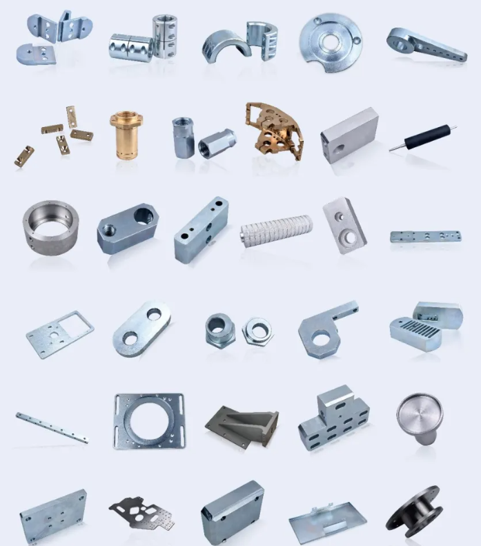
More Production Part
Surface Treatment
Production Process
Why Us