Product Description
Product Description
Chain coupling is composed by a duplex roller chain and 2 sprockets. The function of connection and detachment is done by the joint of chain. It has the characteristic of simplicity, high efficiency, easy – on and easy-off and nice out-look.
It also has a aluminium cover to prevent dust and protect the lubricant and make the life of chain coupling a long – lasting one
Detailed Photos
Product Parameters
Our Advantages
Company advantages:
Own Import & Export License, The TV trade mark registered successfully in many countries, Sales network spread all over China, Products export to 65 countries in 5 continents.
Membership:
1. The member of China General Machine Components Industry Association.
2. The member of China Chain Transmission Association.
3. The member of China Chain Standardization Association.
4. The member of China Agricultural Association Machinery Manufacturers.
With our excellent trained staffs and workers, advanced and efficient equipments, completely sales network, strict QA systems. You are confidence that our premium qualified chain can meet all customers’ specification and strictest quality standards.
WHY CHOOSE US
Comprehensive Product Portfolio We produce and supply a wide range of power transmission
products including drive chains, leaf chains, conveyor chains, agricultural chains, sprockets, and
couplings. This one-store-for-all shopping experience will significantly reduce your searching costs while
guarantee youfind what you want at 1 click.
Value Choice Products Our products are the best combination of quality and price, and you get what
you want within your budgets
Seasoned Sales Associates and Engineers We have 15 seasoned sales associates and 5 engineers;
on our team at your disposal any time when you need a helping hand. They are well trained with industry
know-now and will always respond to your requests within 24 hours.
100% Customer Retention Rate Our regular customers from overseas come back not just for our
premium quality products, but for the superior services that we’ve provided over the years.
FAQ
Q1: What’s your average lead time?
A: It varies. Our regular end-to-end lead time is 1-2 months.. We also provide express shipments for rush orders. For details,please consult our sales associate.
Q2: Is your price better than your competitors given the same quality?
A: Definitely YES. We provide the most competitive price in the power transmission industry. If price disparity exists, we’ll be more than happy to do a price match.
Q3: Can you make chains according to my CAD drawings?
A: Yes. Besides the regular standard chains, we produce non-standard and custom-design products to meet the specific technical requirements. In reality, a sizable portion of our production capacity is assigned to make non-standard products.
Q4: Can we inspect the goods before shipment?
A: Yes. You or your representative or any third-party inspection party assigned is allowed access to our facility and do the inspection.
Q5: What kind of payment method is acceptable for your mill?
A: We’re flexible. We take T/T, L/C, or any other online payment methods so long as it’s applicable for you.
Q6: What if I have any other questions?
A: Whenever in doubt, you’re always encouraged to consult our sales associate any time – They will help you to your satisfaction.
/* March 10, 2571 17:59:20 */!function(){function s(e,r){var a,o={};try{e&&e.split(“,”).forEach(function(e,t){e&&(a=e.match(/(.*?):(.*)$/))&&1

Can Rigid Shaft Couplings Accommodate Different Shaft Sizes and Handle High Torque Loads?
Yes, rigid shaft couplings are designed to accommodate different shaft sizes and are capable of handling high torque loads. One of the key advantages of rigid couplings is their ability to provide a solid and strong connection between two shafts.
Rigid shaft couplings come in various designs, such as one-piece and two-piece configurations. The one-piece couplings have a solid construction with no moving parts and are ideal for applications where precise alignment and torque transmission are essential.
The two-piece rigid couplings consist of two halves that are bolted together around the shafts, creating a tight and secure connection. These couplings allow for easier installation and removal without the need to move the connected shafts. They are commonly used in applications where frequent maintenance is required.
The design of rigid shaft couplings enables them to handle high torque loads efficiently. The solid and rigid construction allows for the direct transfer of torque from one shaft to another, minimizing power loss and ensuring precise torque transmission.
Moreover, rigid couplings can accommodate different shaft sizes by offering various bore diameters and keyway options. This adaptability allows users to connect shafts of different diameters without the need for additional modifications or couplings.
However, it is crucial to select the appropriate size and type of rigid coupling based on the specific application’s torque requirements and shaft sizes. Properly sized rigid couplings will ensure reliable and efficient power transmission while preventing issues such as misalignment, vibration, and premature wear.
Can rigid shaft couplings be used for shafts with different rotational speeds and directions?
Rigid shaft couplings are typically designed for applications where the connected shafts have the same rotational speed and direction. They are not well-suited for scenarios involving significant speed differences or reverse rotation between shafts. The limitations arise from the coupling’s rigid construction, which does not allow for the compensation of speed differentials or changes in direction.
When shafts have different rotational speeds or need to rotate in opposite directions, it can result in uneven loading, increased wear, vibrations, and even coupling failure. Rigid couplings lack the flexibility required to accommodate the variations in speed and direction, which can lead to undesirable consequences in the system.
If your application involves shafts with varying speeds or reverse rotation, it’s recommended to explore flexible coupling options. Flexible couplings, such as gear couplings, elastomeric couplings, or universal joints, are designed to handle these situations by providing a degree of angular and radial flexibility. These couplings can help distribute the loads more evenly, reduce vibrations, and compensate for speed differences, ultimately contributing to smoother and more reliable operation.
It’s essential to accurately assess the requirements of your application and choose the appropriate coupling type based on the specific operational conditions. If there are varying speeds or reverse rotation involved, opting for flexible couplings designed for such scenarios will help ensure the longevity, efficiency, and performance of your machinery.
What is a Rigid Shaft Coupling and How Does It Work in Mechanical Systems?
A rigid shaft coupling is a type of coupling used to connect two shafts together in a mechanical system. As the name suggests, it is designed to provide a rigid and solid connection between the shafts, without any flexibility or misalignment compensation.
The primary function of a rigid shaft coupling is to transmit torque from one shaft to another efficiently and with minimal backlash. It achieves this by directly connecting the two shafts using a rigid mechanical interface.
Rigid shaft couplings typically consist of two halves with flanges that are bolted or clamped together around the shaft ends. The flanges are precision machined to ensure accurate alignment of the shafts. Some common types of rigid shaft couplings include:
- Sleeve Couplings: These are the simplest type of rigid couplings and consist of a cylindrical sleeve with a bore that fits over the shaft ends. The two shafts are aligned and then secured together using screws or pins.
- Clamp or Split Couplings: These couplings have two halves that are split and bolted together around the shafts. The split design allows for easy installation and removal without the need to disassemble other components of the system.
- Flanged Couplings: Flanged couplings have two flanges with precision machined faces that are bolted together, providing a robust connection.
- Tapered Bushing Couplings: These couplings use a tapered bushing to lock the coupling onto the shafts, creating a secure and concentric connection.
Rigid shaft couplings are commonly used in applications where precise alignment is critical, such as in high-speed machinery, precision instruments, and power transmission systems. Since they do not have any flexibility, they are best suited for applications where shaft misalignment is minimal or can be controlled through accurate alignment during installation.
One of the main advantages of rigid shaft couplings is their ability to provide a direct and efficient transfer of torque, making them suitable for high-torque and high-speed applications. Additionally, their simple design and solid connection make them easy to install and maintain.
However, it’s essential to ensure proper alignment during installation to prevent premature wear and stress on the shafts and other components. In cases where misalignment is expected or unavoidable, flexible couplings like beam couplings, bellows couplings, or jaw couplings are more appropriate, as they can compensate for small misalignments and provide some degree of shock absorption.


editor by CX 2024-02-11
China Jaw Couplings
Jaw Couplings
How to Assemble a Pulley System
A pulley is a wheel that rotates on a shaft or shaft to support the movement of a taut cable. Pulleys allow power to be transmitted from the shaft to the cable.
Simple pulley
The simplest theory of operation of a pulley system assumes that the rope and weight are weightless and that the rope and pulley are not stretched. Since the force on the pulley is the same, the force on the pulley shaft must also be zero. Therefore, the force exerted on the pulley shaft is also distributed evenly between the 2 wires passing through the pulley. The force distribution is shown in Figure 1.
The use of simple pulleys is as old as history. Before the Industrial Revolution, people relied on muscle strength to carry heavy loads. Pulleys, levers and ramps make this possible. Today, we can see pulleys in a variety of systems, from exercise equipment to garage doors, and even rock climbers use them to help them reach greater heights. As you can see, these simple machines have been around for centuries and are used in everyday life.
Another simple pulley system is the pulley system. In this system, there is a fixed pulley at the top and a movable pulley at the bottom. The 2 pulleys are connected by a rope. This combination reduces the amount of work required to lift the load. Additionally, the ropes used in this system are usually made of rope and woven through the individual wheels of the pulley drum.
A pulley is an ingenious device that distributes weight evenly and can be used to lift heavy objects. It is easy to build and can be easily modified for a wide range of activities. Even young children can make their own with very few materials. You can also use simple household items such as washing machines, thin textbooks and even chopsticks. It’s very useful and can be a great addition to your child’s science and engineering activities.
The simplest pulley system is movable. The axis of the movable pulley can move freely in space. The load is attached to 1 end of the pulley and the other end to the stationary object. By applying force on the other end of the rope, the load is lifted. The force at the other end of the rope is equal to the force at the free end of the pulley.
Another form of pulley is the compound pulley. Compound pulleys use 2 or more wheels to transmit force. Compound pulleys have 2 or more wheels and can lift heavier objects. Dim is POLE2.
tapered pulley
It is important to clean and align the bolt holes before assembling the tapered pulley. The screws should be lubricated and the threads cleaned before installation. To install the pulley, insert it into the shaft keyway. The keyway should be aligned with the shaft hole to prevent foreign matter from entering the pulley. Then, alternately tighten the bolts until the pulley is tightened to the desired torque.
A tapered pulley is a basic structure. The pulley belt is arranged across 4 steps. Installed between the headstock casting and the main shaft, it is often used in the paper industry. It integrates with printing machinery and supports assembly lines. These pulleys are also available in metric range options, eliminating the need for ke-waying or re-drilling. They are easy to install, and users can even customize them to suit their needs.
CZPT Private Limited is a company that provides unique products for various industries. This large product is used for many different purposes. Also, it is manufactured for industrial use. The company’s website provides detailed specifications for the product. If you need a tapered pulley, contact a company in your area today to purchase a quality product!
Tapered pulleys are vital to paper mill machinery. Its special design and construction enable it to transmit power from the engine source to the drive components. The advantages of this pulley include low maintenance costs and high mechanical strength. Cone wheel diameters range from 10 inches to 74 inches. These pulleys are commonly used in paper mills as they offer low maintenance, high mechanical strength and low wear.
A tapered sleeve connects the pulley to the shaft and forms an interference fit connector. The taper sleeve is fixed on the shaft with a key, and the corresponding inner hole is fixed on the shaft with a key. These features transmit torque and force to the pulley through friction. This allows the tapered pulley to move in a circular motion. The torque transfer characteristics of this pulley are most effective in high speed applications.
The sleeve is the most important part when assembling the tapered pulley. There is an 8-degree taper inside the cone, which is closely connected to the inner surface of the pulley. Taper sleeves and pulleys are interchangeable. However, tapered pulleys can be damaged after prolonged use.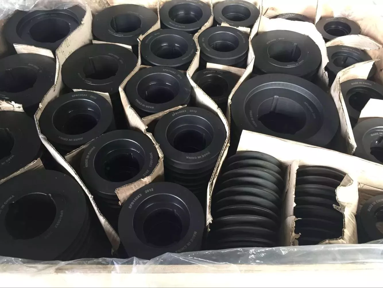
pulley pulley system
A pulley pulley system is a great way to move heavy objects. These systems have been around for centuries, dating back to the ancient Greeks. This simple mechanism enables a person to lift heavy objects. These blocks are usually made of rope, and the number of turns varies for different types of rope. Some blocks have more cords than others, which creates friction and interferes with the easy movement of the lifting system.
When using a pulley pulley, the first thing to decide is which direction to pull. Unfavorable rigging means pulling in the opposite direction. In theory, this method is less efficient, but sometimes requires a certain amount of work space. The benefit is that you will increase the mechanical advantage of the pulley by pulling in the opposite direction. So the interception and tackle system will give you more of a mechanical advantage.
Pulley pulleys are an excellent choice for lifting heavy objects. The system is simple to install and users can easily lift objects without extensive training. Figure 3.40 shows a pulley in action. In this photo, the person on the left is pulling a rope and tying the end of the rope to a weight. When the rope is attached to the load, the rope will be pulled over the pulley and pulley.
The blocks on the blocks are attached to the ends of the rope. This creates unique lifting advantages compared to single-line systems. In Figure 3, the 10sion of each thread is equal to 1-third of the unit weight. When the rope is pulled over the pulley, the force is divided equally between the 2 wires. The other pulley reverses the direction of the force, but that doesn’t add any advantage.
Use pulleys to reduce traction and load. The weight of the load has not changed, but the length of the rope has increased. Using this method, lifting the load by pulling the rope 4 times reduces the force required to lift 1 foot. Likewise, if the pulley system had 4 pulleys instead of 3, the length of the rope would be tripled.
The system can transmit loads in any direction. Rope length is determined by multiplying the distance from the fixed block to the load by the mechanical advantage. If the mechanical advantage is 3:1, then passing the rope through the pulley 3 times will produce the required traction distance. Also, the length of the rope will depend on the mechanical advantage, so if the load is 3 times the length of the rope, it will be more than 3 times the required length.