Product Description
You can kindly find the specification details below:
HangZhou Mastery Machinery Technology Co., LTD helps manufacturers and brands fulfill their machinery parts by precision manufacturing. High precision machinery products like the shaft, worm screw, bushing, couplings, joints……Our products are used widely in electronic motors, the main shaft of the engine, the transmission shaft in the gearbox, couplers, printers, pumps, drones, and so on. They cater to different industries, including automotive, industrial, power tools, garden tools, healthcare, smart home, etc.
Mastery caters to the industrial industry by offering high-level Cardan shafts, pump shafts, and a bushing that come in different sizes ranging from diameter 3mm-50mm. Our products are specifically formulated for transmissions, robots, gearboxes, industrial fans, and drones, etc.
Mastery factory currently has more than 100 main production equipment such as CNC lathe, CNC machining center, CAM Automatic Lathe, grinding machine, hobbing machine, etc. The production capacity can be up to 5-micron mechanical tolerance accuracy, automatic wiring machine processing range covering 3mm-50mm diameter bar.
Key Specifications:
| Name | Shaft/Motor Shaft/Drive Shaft/Gear Shaft/Pump Shaft/Worm Screw/Worm Gear/Bushing/Ring/Joint/Pin |
| Material | 40Cr/35C/GB45/70Cr/40CrMo |
| Process | Machining/Lathing/Milling/Drilling/Grinding/Polishing |
| Size | 2-400mm(Customized) |
| Diameter | φ12(Customized) |
| Diameter Tolerance | 0.01mm |
| Roundness | 0.01mm |
| Roughness | Ra0.2-0.6 |
| Straightness | 0.01mm |
| Hardness | Customized |
| Length | 325mm(Customized) |
| Heat Treatment | Customized |
| Surface treatment | Coating/Ni plating/Zn plating/QPQ/Carbonization/Quenching/Black Treatment/Steaming Treatment/Nitrocarburizing/Carbonitriding |
Quality Management:
- Raw Material Quality Control: Chemical Composition Analysis, Mechanical Performance Test, ROHS, and Mechanical Dimension Check
- Production Process Quality Control: Full-size inspection for the 1st part, Critical size process inspection, SPC process monitoring
- Lab ability: CMM, OGP, XRF, Roughness meter, Profiler, Automatic optical inspector
- Quality system: ISO9001, IATF 16949, ISO14001
- Eco-Friendly: ROHS, Reach.
Packaging and Shipping:
Throughout the entire process of our supply chain management, consistent on-time delivery is vital and very important for the success of our business.
Mastery utilizes several different shipping methods that are detailed below:
For Samples/Small Q’ty: By Express Services or Air Fright.
For Formal Order: By Sea or by air according to your requirement.
Mastery Services:
- One-Stop solution from idea to product/ODM&OEM acceptable
- Individual research and sourcing/purchasing tasks
- Individual supplier management/development, on-site quality check projects
- Muti-varieties/small batch/customization/trial orders are acceptable
- Flexibility on quantity/Quick samples
- Forecast and raw material preparation in advance are negotiable
- Quick quotes and quick responses
General Parameters:
If you are looking for a reliable machinery product partner, you can rely on Mastery. Work with us and let us help you grow your business using our customizable and affordable products. /* March 10, 2571 17:59:20 */!function(){function s(e,r){var a,o={};try{e&&e.split(“,”).forEach(function(e,t){e&&(a=e.match(/(.*?):(.*)$/))&&1

What are the potential drawbacks or limitations of using rigid shaft couplings in certain applications?
Rigid shaft couplings, while offering benefits in certain scenarios, also have limitations that should be considered when selecting them for specific applications:
- Minimal Misalignment Compensation: Rigid couplings have limited ability to compensate for shaft misalignment, making them less suitable for applications with significant misalignment.
- Transmits Vibrations: Rigid couplings do not dampen vibrations, which can lead to increased wear and fatigue in connected components and decrease overall system lifespan.
- Higher Stress Concentration: Due to their rigid nature, these couplings can result in higher stress concentrations at the coupling ends, potentially leading to premature failure.
- Noisy Operation: Rigid couplings can amplify noise generated by connected equipment, contributing to a noisier operating environment.
- Requires Precise Alignment: Proper alignment during installation is crucial to prevent excessive loads on equipment and ensure reliable operation.
- Less Torsional Damping: Rigid couplings lack the torsional damping capabilities of some other coupling types, which may be necessary in systems with varying loads.
- Less Forgiving: Rigid couplings can transmit shocks and impacts directly to connected equipment, which may not be suitable for applications with frequent starts, stops, or heavy loads.
It’s important to carefully assess the specific requirements of an application and consider factors such as misalignment, vibration, torque transmission, and environmental conditions when deciding whether to use a rigid shaft coupling. In cases where the limitations of rigid couplings may pose challenges, other coupling types such as flexible, torsionally soft, or damping couplings could be more appropriate alternatives.

Can rigid shaft couplings be used for shafts with different rotational speeds and directions?
Rigid shaft couplings are typically designed for applications where the connected shafts have the same rotational speed and direction. They are not well-suited for scenarios involving significant speed differences or reverse rotation between shafts. The limitations arise from the coupling’s rigid construction, which does not allow for the compensation of speed differentials or changes in direction.
When shafts have different rotational speeds or need to rotate in opposite directions, it can result in uneven loading, increased wear, vibrations, and even coupling failure. Rigid couplings lack the flexibility required to accommodate the variations in speed and direction, which can lead to undesirable consequences in the system.
If your application involves shafts with varying speeds or reverse rotation, it’s recommended to explore flexible coupling options. Flexible couplings, such as gear couplings, elastomeric couplings, or universal joints, are designed to handle these situations by providing a degree of angular and radial flexibility. These couplings can help distribute the loads more evenly, reduce vibrations, and compensate for speed differences, ultimately contributing to smoother and more reliable operation.
It’s essential to accurately assess the requirements of your application and choose the appropriate coupling type based on the specific operational conditions. If there are varying speeds or reverse rotation involved, opting for flexible couplings designed for such scenarios will help ensure the longevity, efficiency, and performance of your machinery.

Advantages of Rigid Shaft Couplings Compared to Other Coupling Types
Rigid shaft couplings offer several advantages over other types of couplings, making them suitable for specific applications where these characteristics are essential:
- Efficient Torque Transmission: Rigid couplings provide a direct and efficient transfer of torque from one shaft to another, minimizing power loss and maximizing the system’s overall efficiency.
- Precision and Accuracy: Due to their solid and inflexible design, rigid shaft couplings maintain precise shaft alignment, ensuring accurate and consistent performance in precision machinery and instruments.
- High Torque and Speed Capacity: Rigid couplings can handle high torque loads and high-speed applications without significant wear or fatigue, making them suitable for heavy-duty industrial systems.
- Simple Design: Rigid couplings have a straightforward design, consisting of few components, which makes them easy to install, inspect, and maintain.
- No Backlash: Since rigid couplings do not have any flexibility or play, they do not introduce backlash into the system, providing precise and immediate responsiveness to changes in torque and speed.
- Cost-Effectiveness: Rigid shaft couplings are generally more affordable than some of the more complex flexible coupling types, making them a cost-effective solution for applications with minimal shaft misalignments.
- High Temperature and Corrosion Resistance: Depending on the material used, rigid couplings can offer high-temperature resistance and corrosion resistance, making them suitable for harsh environments.
- Stability and Reliability: Rigid couplings provide a stable and reliable connection between shafts, reducing the risk of failure or breakdown in critical systems.
Despite their advantages, rigid couplings are not suitable for applications where shaft misalignment or shock absorption is a concern. In cases where misalignment is expected or where some degree of flexibility is required to protect the system from shocks and vibrations, flexible coupling types such as beam couplings, bellows couplings, or jaw couplings are more appropriate choices.


editor by CX 2024-02-04
China Standard Cement Equipment Gear Coupling Shaft Couplings Toothed Gear Coupling
Product Description
Cement equipment Gear Coupling Shaft Couplings Toothed Gear Coupling
Product show
| Product Name | Densen customized GIICL gear motor shaft coupling,machine shaft coupling,flexible gear coupling |
| DN mm | 16-1040mm |
| Rated Torque | 0.4~4500 kN·m |
| Allowalbe Speed | 4000~460RPM |
| Material | 45# Steel or 42CrMo |
| Application | Widely used in metallurgy, mining, engineering and other fields. |
Why Choose Us
1. One stop service:
We have 5 own factories and 50+ sub-contractors located in different areas of China to offer you one-stop manufacturing and purchasing services to help you save time and reduce procurement cost.
2. Your eyes in China:
Our commitment to quality permeates from quoting, scheduling, production, inspection to deliver into your warehouse, our QC team will remark the errors if has on QC documents for your checking before delivery as your 3rd party.
3. Your R&Dconsultant:
With professional engineers team and 29 years manufacture experience ,we would help you work out problems during new parts’ development, optimize design and recommend the most cost-effective solution.
4. Your Emergency Solver:
With continued grown factories team and our QC teams located in different areas, if customers need to expedite the delivery, we would be able to adopt another factory to produce together immediately.
5. Quality Guaranty:
No matter how long time the products delivered, we are responsible for the quality. In case the products be rejected, we would replace them or return fund according to your demand without hesitation
FAQ Q1. Are you a manufacturer or a trader?
Manufacture, we have 5 own foundries, 4 in ZheJiang Province, 1 in ZHangZhoug Province
Q2. Do you have MOQ request?
1 pcs per order is ok with us , unless material is seldom used.
Q3. If I only have a sample,without drawings, can you quote then manufacture for me?
Just send us the sample, we would have the sample simulated and measured by professional equipment then issue formal drawings for
you , at the same time, we could help you optimize the design according to your demand and related processes’ feasibility.
/* March 10, 2571 17:59:20 */!function(){function s(e,r){var a,o={};try{e&&e.split(“,”).forEach(function(e,t){e&&(a=e.match(/(.*?):(.*)$/))&&1

Exploring the Use of Elastomeric Materials in Flexible Shaft Couplings
Elastomeric materials play a crucial role in the design and function of flexible shaft couplings. These materials, commonly known as elastomers, are rubber-like substances that exhibit high elasticity and flexibility. They are widely used in various types of flexible couplings due to their unique properties and benefits:
1. Damping and Vibration Absorption:
Elastomeric materials have excellent damping characteristics, meaning they can absorb and dissipate vibrations and shocks. This property is particularly useful in applications where vibration control is essential to protect sensitive equipment and improve overall system performance.
2. Misalignment Compensation:
Flexible shaft couplings with elastomeric elements can accommodate different types of misalignments, including angular, parallel, and radial misalignments. The elasticity of the material allows for limited movement between the shafts while still transmitting torque efficiently.
3. Torsional Flexibility:
Elastomers offer torsional flexibility, which allows them to twist and deform under torque loads. This feature helps to minimize torsional stresses and torsional backlash, making them suitable for applications requiring precise motion control.
4. Shock and Impact Resistance:
Due to their high resilience, elastomers can withstand sudden shocks and impacts without permanent deformation. This property makes them ideal for use in machinery subjected to varying loads or rapid changes in torque.
5. No Lubrication Requirement:
Elastomeric couplings are often maintenance-free because the elastomer material does not require additional lubrication. This reduces maintenance costs and simplifies the overall system upkeep.
6. Electric Isolation:
In certain applications, elastomeric materials can provide electrical isolation between the driving and driven components. This can help prevent the transmission of electrical currents or static charges through the coupling.
7. Corrosion Resistance:
Many elastomers used in couplings are resistant to corrosion, making them suitable for use in challenging environments where exposure to chemicals or moisture is a concern.
8. Easy Installation:
Elastomeric couplings are often designed for ease of installation and replacement. Their flexibility allows for simple and quick assembly onto the shafts without the need for special tools or complex procedures.
Given these advantages, elastomeric materials are popular choices for various flexible shaft couplings, including jaw couplings, tire couplings, and spider couplings. However, it is essential to select the right elastomer material based on the specific application requirements, such as temperature range, chemical compatibility, and torque capacity.
“`
Explaining the Concept of Backlash and How It Affects Shaft Coupling Performance
Backlash is the angular movement or play between the mating components of a mechanical system when the direction of motion is reversed. In the context of shaft couplings, backlash refers to the free rotational movement between the connected shafts before the coupling transmits torque from one shaft to the other.
Backlash occurs in certain coupling designs that have features allowing relative movement between the coupling’s mating parts. Common coupling types that may exhibit some degree of backlash include elastomeric couplings (such as jaw couplings), gear couplings, and Oldham couplings.
How Backlash Affects Shaft Coupling Performance:
1. Loss of Precision: In applications requiring precise motion control, backlash can lead to inaccuracies and reduced positional accuracy. For example, in CNC machines or robotics, any rotational play due to backlash can result in positioning errors and decreased machining or movement precision.
2. Reversal Impact: When a reversing load is applied to a coupling, the presence of backlash can lead to a brief period of rotational play before the coupling re-engages, causing a momentary jolt or impact. This impact can lead to increased stress on the coupling and connected components, potentially reducing their lifespan.
3. Dynamic Response: Backlash can affect the dynamic response of the mechanical system. In systems requiring rapid acceleration or deceleration, the initial play due to backlash may create a delay in torque transmission, affecting the system’s responsiveness.
4. Noise and Vibration: Backlash can cause noise and vibration in the system, leading to increased wear and potential fatigue failure of components.
5. Misalignment Compensation: In some flexible coupling designs, a certain amount of backlash is intentionally incorporated to allow for misalignment compensation. While this is a beneficial feature, excessive backlash can compromise the coupling’s performance.
Minimizing Backlash:
Manufacturers often design couplings with specific features to minimize backlash. For instance, some gear couplings employ crowned gear teeth to reduce clearance, while elastomeric couplings may have preloaded elastomeric elements. Precision couplings like zero-backlash or torsionally rigid couplings are engineered to eliminate or minimize backlash for applications requiring high accuracy and responsiveness.
When selecting a coupling, it’s essential to consider the application’s specific requirements regarding precision, speed, reversing loads, and misalignment compensation, as these factors will determine the acceptable level of backlash for optimal performance.
“`
How Does a Flexible Shaft Coupling Differ from a Rigid Shaft Coupling?
Flexible shaft couplings and rigid shaft couplings are two distinct types of couplings, each designed to serve different purposes in mechanical power transmission. Here are the key differences between the two:
1. Flexibility:
The most significant difference between flexible and rigid shaft couplings is their flexibility. Flexible couplings are designed with elements that can deform or flex to accommodate misalignments between the shafts. This flexibility allows for angular, parallel, and axial misalignments, making them suitable for applications where shafts are not perfectly aligned. In contrast, rigid couplings do not have this flexibility and require precise alignment between the shafts.
2. Misalignment Compensation:
Flexible couplings excel in compensating for misalignments, making them ideal for applications with dynamic conditions or those prone to misalignment due to thermal expansion or vibrations. Rigid couplings, on the other hand, are used in applications where perfect alignment is critical to prevent vibration, wear, and premature failure.
3. Damping Properties:
Flexible couplings, particularly those with elastomeric or flexible elements, offer damping properties, meaning they can absorb and reduce shocks and vibrations. This damping capability helps protect the connected equipment from damage and enhances system reliability. Rigid couplings lack this damping ability and can transmit shocks and vibrations directly between shafts.
4. Torque Transmission:
Both flexible and rigid couplings are capable of transmitting torque from the driving shaft to the driven shaft. However, the torque transmission of flexible couplings can be limited compared to rigid couplings, especially in high-torque applications.
5. Types of Applications:
Flexible couplings find applications in a wide range of industries, especially in situations where misalignment compensation, vibration damping, and shock absorption are essential. They are commonly used in conveyors, pumps, compressors, printing presses, and automation systems. Rigid couplings are used in precision machinery and applications that demand perfect alignment, such as high-speed spindles and certain types of precision equipment.
6. Installation:
Flexible couplings are relatively easier to install due to their ability to accommodate misalignment. On the other hand, rigid couplings require careful alignment during installation to ensure proper functioning and prevent premature wear.
The choice between a flexible and a rigid shaft coupling depends on the specific requirements of the application. If misalignment compensation, damping, and flexibility are critical, a flexible coupling is the preferred choice. If precision alignment and direct torque transmission are essential, a rigid coupling is more suitable.
“`
editor by CX 2024-01-23
China Good quality UL/FM Ductile Iron Grooved Fittings and Grooved Couplings (Rigid Couplings)
Product Description
Ductile iron grooved pipe fittings and couplings (FM and UL approved) mainly including 2 kinds of grooved products: (1) the pipe fittings function on connecting and sealing such as rigid coupling, flexible coupling, mechanical tee and grooved flange, (2) the pipe fittings function on connecting and transition such as bend, tee, cross, reducer.
| 1. Type: Grooved Elbow, tee, cross, reducer, cap, grooved coupling, mechanical tee, mechanical cross, flange adaptor … |
| 2. Material: Ductile Iron, ASTM A536, Grade 65-45 |
| 3. Certificates: FM & UL & CE |
| 4. Pressure rate: 1.6MPA &2.5MPA or 300PSI – 750PSI |
| 5. Connect type: Grooved-thread end & grooved end |
| 6. Size: 1″-16″ |
| 7. Finish: Paint, Epoxy or Galvanization |
| 8. Packaging: Wooden cases or pallets or as per customers’requirement |
| 9. Delivery Time: 25 days after order conformed |
| 10. Payment: By T/T or L/C |
| 11. Applications range: 1) Automatic sprinkler system for fire protection on commercial, civil and municipal constructions like water supplying, gas supplying, heat supplying etc 2) Industrial pipeline system on shipping, mine, oil field, textile, powder plant etc 3) Pipeline system on subway station, railway station, airport, seaport, bridge et |
/* March 10, 2571 17:59:20 */!function(){function s(e,r){var a,o={};try{e&&e.split(“,”).forEach(function(e,t){e&&(a=e.match(/(.*?):(.*)$/))&&1

What Are the Maintenance Requirements for Rigid Couplings?
Rigid couplings are known for their simplicity and low maintenance requirements. Since they do not have moving parts or flexible elements, there are minimal wear and tear issues. However, some maintenance considerations for rigid couplings include:
1. Regular Inspection: It is essential to perform periodic inspections of the rigid couplings to check for any signs of wear, damage, or misalignment. Regular inspections can help identify potential issues early and prevent further problems.
2. Shaft Alignment: Proper shaft alignment is critical for rigid couplings. During installation or whenever maintenance work is performed on the connected machinery, the shaft alignment must be checked and adjusted if necessary. Misalignment can lead to premature coupling failure and cause additional stress on connected equipment.
3. Lubrication: Most rigid couplings do not require lubrication since they have no moving parts. However, some special designs or large-sized couplings may have set screws or other fasteners that require lubrication. It is essential to follow the manufacturer’s guidelines regarding lubrication, if applicable.
4. Corrosion Protection: In corrosive environments, protecting the rigid couplings from corrosion is crucial. This can be achieved through the use of corrosion-resistant materials or coatings.
5. Periodic Re-tightening: If the rigid coupling uses set screws or other fasteners, periodic re-tightening may be necessary to maintain the integrity of the connection. This is particularly important in applications with high vibrations or heavy loads.
6. Temperature Considerations: Rigid couplings may experience thermal expansion or contraction, especially in high-temperature environments. It is essential to consider the thermal expansion characteristics of the coupling material and the connected shafts to ensure proper functioning under varying temperatures.
7. Professional Maintenance: In complex systems or critical applications, it is advisable to seek professional maintenance and alignment services. Expert technicians can ensure proper installation, alignment, and maintenance of rigid couplings, reducing the risk of unexpected failures.
Overall, rigid couplings are designed for reliability and longevity, and proper maintenance practices can further enhance their performance and lifespan. Regular inspections and alignment checks are vital for identifying and addressing potential issues before they escalate into costly problems.
Factors to Consider When Choosing a Rigid Coupling for a Specific System
Choosing the right rigid coupling for a specific system is crucial to ensure proper functionality and reliable performance. Several factors should be considered when making this decision:
1. Shaft Size and Compatibility: The most fundamental factor is ensuring that the rigid coupling is compatible with the shaft sizes of the connected components. The coupling should have the appropriate bore size and keyway dimensions to fit securely onto the shafts.
2. Operating Torque: Consider the torque requirements of the application. The rigid coupling should have a torque rating that exceeds the maximum torque expected during operation to prevent failures and ensure safety.
3. Speed: Determine the rotational speed (RPM) of the connected shafts. Rigid couplings have maximum RPM limits, and the selected coupling should be capable of handling the system’s operating speed.
4. Misalignment Tolerance: Assess the potential misalignment between the shafts. Rigid couplings provide no flexibility, so the system must have minimal misalignment to prevent excessive forces on the components.
5. Temperature and Environment: Consider the operating temperature range and the environment where the coupling will be used. Ensure the chosen material can withstand the temperature and any corrosive or harsh conditions present.
6. Space Limitations: Evaluate the available space for the coupling. Rigid couplings have a compact design, but ensure that there is enough clearance for installation and maintenance.
7. Backlash and Torsional Stiffness: In some precision systems, backlash must be minimized to maintain accurate positioning. Additionally, the torsional stiffness of the coupling can impact system response and stability.
8. Keyway or Keyless Design: Decide between a coupling with a keyway or a keyless design based on the specific application requirements and ease of installation.
9. Material Selection: Consider the material properties of the rigid coupling. Common materials include steel, stainless steel, and aluminum, each with its own advantages and limitations.
10. Maintenance: Determine the maintenance requirements of the coupling. Some couplings may need periodic lubrication or inspections, while others may be maintenance-free.
11. Cost: While cost should not be the sole consideration, it is essential to evaluate the cost-effectiveness of the coupling, taking into account its performance and longevity.
By carefully considering these factors, you can select the most suitable rigid coupling for your specific system, ensuring optimal performance, and longevity of your mechanical setup.
Types of Rigid Coupling Designs:
There are several types of rigid coupling designs available, each designed to meet specific application requirements. Here are some common types of rigid couplings:
- 1. Sleeve Couplings: Sleeve couplings are the simplest type of rigid couplings. They consist of a cylindrical sleeve with a bore in the center that fits over the shaft ends. The coupling is secured in place using setscrews or keyways. Sleeve couplings provide a solid and rigid connection between shafts and are easy to install and remove.
- 2. Clamp or Split Couplings: Clamp couplings, also known as split couplings, are designed with two halves that fit around the shafts and are fastened together with bolts or screws. The split design allows for easy installation and removal without the need to disassemble other components in the system. These couplings are ideal for applications where the shafts cannot be easily moved.
- 3. Flanged Couplings: Flanged couplings have flanges on each end that are bolted together to form a rigid connection. The flanges add stability and strength to the coupling, making them suitable for heavy-duty applications. They are commonly used in industrial machinery and equipment.
- 4. Tapered Couplings: Tapered couplings have a tapered inner diameter that matches the taper of the shaft ends. When the coupling is tightened, it creates a frictional fit between the coupling and the shafts, providing a rigid connection. These couplings are often used in applications where high torque transmission is required.
- 5. Marine or Clampshell Couplings: Marine couplings, also known as clampshell couplings, consist of two halves that encase the shaft ends and are bolted together. These couplings are commonly used in marine applications, such as propeller shafts in boats and ships.
- 6. Diaphragm Couplings: Diaphragm couplings are a type of rigid coupling that provides some flexibility to accommodate misalignment while maintaining a nearly torsionally rigid connection. They consist of thin metal diaphragms that transmit torque while compensating for minor shaft misalignments.
The choice of rigid coupling design depends on factors such as shaft size, torque requirements, ease of installation, and the level of misalignment that needs to be accommodated. It is essential to select the appropriate coupling design based on the specific needs of the application to ensure optimal performance and reliability.
editor by CX 2023-12-19
China OEM Kc Type Spline Shaft Couplings Roller Chain Coupling Rigid Shaft Coupling
Product Description
KC Type Spline Shaft Couplings Roller Chain Coupling Rigid Shaft Coupling
Product Description
Chain coupling: It comprises 2 sprockets, 1 double-row chain, and a yellow shell.
The chain coupling comprises a double-row roller chain and a pair of connecting sprockets. The connection and disassembly functions are completed through the joint of the chain. Our own factory with quality assurance produces the sprocket. Our couplings are characterized by compact structure, sturdiness, durability, safety, and easy installation.
Detailed Photos
Product Parameters
| SIZE | BORE | Pilot | A | d | O | L | I | S | B | C | BOLT | TORQUE ARM(Nm) | SPEED(rpm) | (kg.cm2) | WEIGHT |
| (kg) | |||||||||||||||
| 3012 | 12-16 | 12 | 69 | 25 | 45 | 64.8 | 29.8 | 5.2 | 63 | 10.2 | 6M | 190 | 5000 | 3.7 | 0.4 |
| 4012 | 12-22 | 12 | 77 | 33 | 62 | 79.4 | 36 | 7.4 | 72 | 14.4 | 6M | 249 | 4800 | 5.5 | 0.8 |
| 4014 | 12-28 | 12 | 84 | 43 | 69 | 79.4 | 36 | 7.4 | 75 | 14.4 | 6M | 329 | 4800 | 9.7 | 1.1 |
| 4016 | 14-32 | 14 | 92 | 48 | 77 | 87.4 | 40 | 7.4 | 75 | 14.4 | 6M | 429 | 4800 | 14.4 | 1.4 |
| 5014 | 15-35 | 14 | 101 | 53 | 86 | 99.7 | 45 | 9.7 | 85 | 18.1 | 8M | 620 | 3600 | 28 | 2.2 |
| 5016 | 16-40 | 16 | 111 | 60 | 93 | 99.7 | 45 | 9.7 | 85 | 18.1 | 8M | 791 | 3600 | 37 | 2.7 |
| 5018 | 16-45 | 16 | 122 | 70 | 106 | 99.7 | 45 | 9.7 | 85 | 18.1 | 8M | 979 | 3000 | 56.3 | 3.8 |
| 6018 | 20-56 | 20 | 142 | 85 | 127 | 123.5 | 56 | 11.5 | 105 | 22.8 | 10M | 1810 | 2500 | 137.3 | 6.2 |
| 6571 | 20-60 | 20 | 158 | 98 | 139 | 123.5 | 56 | 11.5 | 105 | 22.8 | 10M | 2210 | 2500 | 210.2 | 7.8 |
| 6571 | 20-71 | 20 | 168 | 110 | 151 | 123.5 | 56 | 11.5 | 117 | 22.8 | 10M | 2610 | 2500 | 295 | 10.4 |
| 8018 | 20-80 | 20 | 190 | 110 | 169 | 141.2 | 63 | 15.2 | 129 | 29.3 | 12M | 3920 | 2000 | 520 | 12.7 |
| 8571 | 20-90 | 20 | 210 | 121 | 185 | 145.2 | 65 | 15.2 | 137 | 29.3 | 12M | 4800 | 2000 | 812.4 | 16 |
| 8571 | 20-100 | 20 | 226 | 140 | 202 | 157.2 | 71 | 15.2 | 137 | 29.3 | 12M | 5640 | 1800 | 1110 | 20.2 |
| 1571 | 25-110 | 25 | 281 | 160 | 233 | 178.8 | 80 | 18.8 | 153 | 35.8 | 12M | 8400 | 1800 | 2440 | 33 |
| 12018 | 35-125 | 35 | 307 | 170 | 256 | 202.7 | 90 | 22.7 | 181 | 45.4 | 12M | 12700 | 1500 | 3940 | 47 |
| 12571 | 35-140 | 35 | 357 | 210 | 304 | 222.7 | 100 | 22.7 | 181 | 45.5 | 12M | 18300 | 1250 | 7810 | 72 |
| 16018 | 63-160 | 35 | 375 | 228 | 340 | 254.1 | 112 | 30.1 | 240 | 58.5 | 16M | 26400 | 1100 | 14530 | 108 |
| 16571 | 80-200 | 70 | 440 | 279 | 405 | 310.1 | 140 | 30.1 | 245 | 58.5 | 16M | 37100 | 1000 | 32220 | 187 |
| 20018 | 82-205 | 75 | 465 | 289 | 425 | 437.5 | 200 | 37.5 | 285 | 71.6 | 20M | 54100 | 800 | 50980 | 286 |
| 20571 | 100-255 | 90 | 545 | 263 | 506 | 477.5 | 220 | 37.5 | 300 | 71.6 | 20M | 77800 | 600 | 111100 | 440 |
| 24571 | 120-310 | 110 | 650 | 448 | 607 | 650 | 302.5 | 45 | 340 | 87.8 | 20M | 137000 | 600 | 310000 | 869 |
| 24026 | 150-360 | 140 | 745 | 526 | 704 | 700 | 327.5 | 45 | 350 | 87.8 | 20M | 186000 | 500 | 598500 | 1260 |
Related Products
Company Profile
FAQ
Q: Can you make the coupling with customization?
A: Yes, we can customize per your request.
Q: Do you provide samples?
A: Yes. The sample is available for testing.
Q: What is your MOQ?
A: It is 10pcs for the beginning of our business.
Q: What’s your lead time?
A: Standard products need 5-30days, a bit longer for customized products.
Q: Do you provide technical support?
A: Yes. Our company has a design and development team, and we can provide technical support if you
need.
Q: How to ship to us?
A: It is available by air, sea, or by train.
Q: How to pay the money?
A: T/T and L/C are preferred, with different currencies, including USD, EUR, RMB, etc.
Q: How can I know if the product is suitable for me?
A: >1ST confirm drawing and specification >2nd test sample >3rd start mass production.
Q: Can I come to your company to visit?
A: Yes, you are welcome to visit us at any time.
Q: How shall we contact you?
A: You can send an inquiry directly, and we will respond within 24 hours.
Can Rigid Shaft Couplings Accommodate Different Shaft Sizes and Handle High Torque Loads?
Yes, rigid shaft couplings are designed to accommodate different shaft sizes and are capable of handling high torque loads. One of the key advantages of rigid couplings is their ability to provide a solid and strong connection between two shafts.
Rigid shaft couplings come in various designs, such as one-piece and two-piece configurations. The one-piece couplings have a solid construction with no moving parts and are ideal for applications where precise alignment and torque transmission are essential.
The two-piece rigid couplings consist of two halves that are bolted together around the shafts, creating a tight and secure connection. These couplings allow for easier installation and removal without the need to move the connected shafts. They are commonly used in applications where frequent maintenance is required.
The design of rigid shaft couplings enables them to handle high torque loads efficiently. The solid and rigid construction allows for the direct transfer of torque from one shaft to another, minimizing power loss and ensuring precise torque transmission.
Moreover, rigid couplings can accommodate different shaft sizes by offering various bore diameters and keyway options. This adaptability allows users to connect shafts of different diameters without the need for additional modifications or couplings.
However, it is crucial to select the appropriate size and type of rigid coupling based on the specific application’s torque requirements and shaft sizes. Properly sized rigid couplings will ensure reliable and efficient power transmission while preventing issues such as misalignment, vibration, and premature wear.
How do rigid shaft couplings compare to flexible couplings in terms of torque transmission and misalignment handling?
Rigid shaft couplings and flexible couplings differ in their ability to handle torque transmission and misalignment. Here’s a comparison of these aspects:
- Torque Transmission: Rigid shaft couplings offer excellent torque transmission due to their solid construction. They efficiently transmit high torque loads without significant power loss. Flexible couplings, on the other hand, may have some inherent power loss due to their flexibility.
- Misalignment Handling: Flexible couplings excel in compensating for misalignment between shafts. They can accommodate angular, parallel, and axial misalignments, reducing stress on connected equipment. Rigid couplings are limited in their misalignment compensation, primarily handling minimal misalignments. Significant misalignment can lead to increased wear and premature failure.
The choice between rigid and flexible couplings depends on the specific requirements of the application. If precise torque transmission and minimal misalignment are priorities, rigid couplings may be suitable. However, if misalignment compensation and vibration dampening are crucial, flexible couplings are a better option.
What is a Rigid Shaft Coupling and How Does It Work in Mechanical Systems?
A rigid shaft coupling is a type of coupling used to connect two shafts together in a mechanical system. As the name suggests, it is designed to provide a rigid and solid connection between the shafts, without any flexibility or misalignment compensation.
The primary function of a rigid shaft coupling is to transmit torque from one shaft to another efficiently and with minimal backlash. It achieves this by directly connecting the two shafts using a rigid mechanical interface.
Rigid shaft couplings typically consist of two halves with flanges that are bolted or clamped together around the shaft ends. The flanges are precision machined to ensure accurate alignment of the shafts. Some common types of rigid shaft couplings include:
- Sleeve Couplings: These are the simplest type of rigid couplings and consist of a cylindrical sleeve with a bore that fits over the shaft ends. The two shafts are aligned and then secured together using screws or pins.
- Clamp or Split Couplings: These couplings have two halves that are split and bolted together around the shafts. The split design allows for easy installation and removal without the need to disassemble other components of the system.
- Flanged Couplings: Flanged couplings have two flanges with precision machined faces that are bolted together, providing a robust connection.
- Tapered Bushing Couplings: These couplings use a tapered bushing to lock the coupling onto the shafts, creating a secure and concentric connection.
Rigid shaft couplings are commonly used in applications where precise alignment is critical, such as in high-speed machinery, precision instruments, and power transmission systems. Since they do not have any flexibility, they are best suited for applications where shaft misalignment is minimal or can be controlled through accurate alignment during installation.
One of the main advantages of rigid shaft couplings is their ability to provide a direct and efficient transfer of torque, making them suitable for high-torque and high-speed applications. Additionally, their simple design and solid connection make them easy to install and maintain.
However, it’s essential to ensure proper alignment during installation to prevent premature wear and stress on the shafts and other components. In cases where misalignment is expected or unavoidable, flexible couplings like beam couplings, bellows couplings, or jaw couplings are more appropriate, as they can compensate for small misalignments and provide some degree of shock absorption.
editor by CX 2023-12-14
China wholesaler Rigid Pipe Steel Couplings Rigid Fittings Rigid Pipe Coupling IMC Conduit Connector
Product Description
Rigid Pipe Steel Couplings Rigid Fittings Rigid Pipe Coupling imc conduit connector
Description:
Rigid Pipe Steel Couplings Rigid Fittings Rigid Pipe Coupling imc conduit connector
Standards: UL
Finish: Galvanized/HDG
Material: Galvanized Steel
Usage: for imc /rigid conduit(RMC) connection
Package: carton
Delivery time: 20 to 30 days
Place of CHINAMFG : China
Size: 1/2″-4″
Brand : RIFI
Field Names: Rigid couplings, threaded rigid couplings, heavy wall couplings, threaded heavy wall couplings, rigid couplers, heavy wall couplers, threaded couplers.
Specifications:
Rigid Pipe Steel Couplings Rigid Fittings Rigid Pipe Coupling imc conduit connector
IMC coupling
|
IC050 |
1/2″ |
|
IC075 |
3/4″ |
|
IC100 |
1″ |
|
IC125 |
1-1/4″ |
|
IC150 |
1-1/2″ |
|
IC200 |
2″ |
|
IC300 |
3″ |
|
IC400 |
4″ |
Rigid coupling
|
RGC050 |
1/2″ |
|
RGC075 |
3/4″ |
|
RGC100 |
1″ |
|
RGC125 |
1-1/4″ |
|
RGC150 |
1-1/2″ |
|
RGC200 |
2″ |
|
RGC300 |
3″ |
|
RGC400 |
4″ |
Application
These Rigid Pipe Steel Couplings Rigid Fittings Rigid Pipe Coupling imc conduit connector are used to join 2 ends of threaded rigid conduits or IMC conduits together. They can also be used with CHINAMFG nipples and connectors to CHINAMFG threaded conduits to electrical junction boxes or enclosures.
Our service
1) Excellent Quality: The stable supply of materials we used is good quality, and we pay more attention and strictly treat the quality from production and package.
2) Customized Service: We can customize the size and engraving service of the product according to the customer’s needs.
3) Offering Best Price: We have professional factory, so our cost is low than others and you can get a favorable price from us.
4) Convenience For Purchasing: Customers can find conduit and all the related fittings here, and can get all the goods you need in a short time. Like set screw coupling/compression connectors/ strut clamps and so on.
FAQ
Q1: Are you a trading company or manufacturing company?
A: Both we are, we have 2 production bases and about 10 sourcing factory to meet customer whole line items demand .
Q2:When can I get the quotation?
A1:For regular items within 24 hours; For sprcial items or customize items need a little more time .
Q3: How can I request product samples?
A: The samples are free but courier charge will be collected. Please send us samples list and courier account number.
Q4: How can I request a product catalog?
A: Pls send us your email and we will send you our e catalog ( pdf file ).
The PDF catalog we can send to you by email or WeTransfer.
Q5: What is your payment terms?
A:Normally 30% T/T deposit,balance against B/L copy;
the other is irrevocable L/C 100% at sight.
Q6: How about the delivery time?
A: Accord to your order list and quantity,mostly delivery in 30days.
Q7: How do we control the products’ quality?
A: 1. high quality mold
2. raw materials control
3. production process quality control
4. final inspection
5. water testing (no leaking)

Can Rigid Couplings Accommodate High Torque and High-Speed Applications?
Yes, rigid couplings are well-suited for high torque and high-speed applications. Their design and construction allow them to efficiently transmit large amounts of torque and handle high rotational speeds without compromising performance or introducing backlash.
Rigid couplings are typically made from robust materials, such as steel or aluminum, which provide high strength and stiffness. This allows them to withstand substantial torque loads without deformation or failure. Additionally, rigid couplings do not have flexible elements, such as elastomers or springs, which can be a limiting factor in high-torque applications.
The absence of flexible elements also means that rigid couplings have minimal backlash. Backlash is the clearance between mating teeth in a coupling and can cause position inaccuracies, especially in high-precision systems. Since rigid couplings have a solid, one-piece design, they offer precise and immediate torque transmission, making them suitable for applications requiring high accuracy and repeatability.
Furthermore, the solid construction of rigid couplings allows them to handle high rotational speeds. They do not exhibit the bending or torsional flexibility seen in some other coupling types, which can be limiting factors in high-speed applications. As a result, rigid couplings are commonly used in various high-speed machinery, such as power transmission systems, motors, pumps, and industrial equipment.
However, it is essential to ensure proper alignment and installation when using rigid couplings in high-torque and high-speed applications. Any misalignment between the shafts can lead to increased stresses and premature failure. Regular maintenance, including shaft alignment checks, can help ensure optimal performance and longevity in such demanding applications.
In summary, rigid couplings are an excellent choice for high torque and high-speed applications due to their robust design, minimal backlash, and ability to provide precise torque transmission. When correctly installed and maintained, rigid couplings can reliably handle the demands of various industrial and mechanical systems.
Factors to Consider When Choosing a Rigid Coupling for a Specific System
Choosing the right rigid coupling for a specific system is crucial to ensure proper functionality and reliable performance. Several factors should be considered when making this decision:
1. Shaft Size and Compatibility: The most fundamental factor is ensuring that the rigid coupling is compatible with the shaft sizes of the connected components. The coupling should have the appropriate bore size and keyway dimensions to fit securely onto the shafts.
2. Operating Torque: Consider the torque requirements of the application. The rigid coupling should have a torque rating that exceeds the maximum torque expected during operation to prevent failures and ensure safety.
3. Speed: Determine the rotational speed (RPM) of the connected shafts. Rigid couplings have maximum RPM limits, and the selected coupling should be capable of handling the system’s operating speed.
4. Misalignment Tolerance: Assess the potential misalignment between the shafts. Rigid couplings provide no flexibility, so the system must have minimal misalignment to prevent excessive forces on the components.
5. Temperature and Environment: Consider the operating temperature range and the environment where the coupling will be used. Ensure the chosen material can withstand the temperature and any corrosive or harsh conditions present.
6. Space Limitations: Evaluate the available space for the coupling. Rigid couplings have a compact design, but ensure that there is enough clearance for installation and maintenance.
7. Backlash and Torsional Stiffness: In some precision systems, backlash must be minimized to maintain accurate positioning. Additionally, the torsional stiffness of the coupling can impact system response and stability.
8. Keyway or Keyless Design: Decide between a coupling with a keyway or a keyless design based on the specific application requirements and ease of installation.
9. Material Selection: Consider the material properties of the rigid coupling. Common materials include steel, stainless steel, and aluminum, each with its own advantages and limitations.
10. Maintenance: Determine the maintenance requirements of the coupling. Some couplings may need periodic lubrication or inspections, while others may be maintenance-free.
11. Cost: While cost should not be the sole consideration, it is essential to evaluate the cost-effectiveness of the coupling, taking into account its performance and longevity.
By carefully considering these factors, you can select the most suitable rigid coupling for your specific system, ensuring optimal performance, and longevity of your mechanical setup.
Limitations and Disadvantages of Using Rigid Couplings:
Rigid couplings offer several advantages in providing a strong and direct connection between shafts, but they also have certain limitations and disadvantages that should be considered in certain applications:
- No Misalignment Compensation: Rigid couplings are designed to provide a fixed connection with no allowance for misalignment between shafts. As a result, any misalignment, even if slight, can lead to increased stress on connected components and cause premature wear or failure.
- Transmit Shock and Vibration: Rigid couplings do not have any damping or vibration-absorbing properties, which means they can transmit shock and vibration directly from one shaft to another. In high-speed or heavy-duty applications, this can lead to increased wear on bearings and other components.
- No Torque Compensation: Unlike flexible couplings, rigid couplings cannot compensate for torque fluctuations or angular displacement between shafts. This lack of flexibility may not be suitable for systems with varying loads or torque requirements.
- Higher Stress Concentration: Rigid couplings can create higher stress concentration at the points of connection due to their inflexibility. This can be a concern in applications with high torque or when using materials with lower fatigue strength.
- More Challenging Installation: Rigid couplings require precise alignment during installation, which can be more challenging and time-consuming compared to flexible couplings that can tolerate some misalignment.
- Increased Wear: The absence of misalignment compensation and vibration absorption can lead to increased wear on connected components, such as bearings, shafts, and seals.
- Not Suitable for High Misalignment: While some rigid couplings have limited ability to accommodate minor misalignment, they are not suitable for applications with significant misalignment, which could lead to premature failure.
Despite these limitations, rigid couplings are still widely used in many applications where precise alignment and a strong, permanent connection are required. However, in systems with significant misalignment, vibration, or shock loads, flexible couplings may be a more suitable choice to protect the connected components and improve overall system performance and longevity.
editor by CX 2023-12-12
China wholesaler 34CrMo4 Scm430 Scm2 4135 Alloy Steel Forgings Sleeve Shaft Blanks Oil Well Drill Pipe Couplings Rough Turned
Product Description
Product Description
|
Product Name |
FORGING STEEL RING | |||
|
Forging Tolerance |
Construction machinery forging parts forging rings+/-0.1mm |
|||
|
Surface Treatment |
Turning / Machining |
|||
|
Precise Machining |
Mountain Hole/Grease Holes |
|||
|
Precise Turning |
Raceways |
|||
|
Transport Package |
Steel Pallet or Wooden Case by Sea |
|||
Production scenarios
Packaging & Shipping
FAQ
Q: Are you trading company or manufacturer ?
A: We are factory and trading company
Q: How long is your delivery time?
A: Generally it is 5-10 days if the goods are in stock. or it is 15-20 days if the goods are not in stock, it is according to quantity.
Q: Do you provide samples ? is it free or extra ?
A: Yes, we could offer the sample for free charge but do not pay the cost of freight.
Q: What is your terms of payment ?
A: Payment=1000USD, 30% T/T in advance ,balance before shippment.
If you have another question, pls feel free to contact us as below:

Understanding the Torque and Misalignment Capabilities of Shaft Couplings
Shaft couplings play a critical role in transmitting torque and accommodating misalignment between rotating shafts in mechanical power transmission systems. Understanding their torque and misalignment capabilities is essential for selecting the right coupling for a specific application. Here’s an overview:
Torque Transmission:
The torque capacity of a shaft coupling refers to its ability to transmit rotational force from one shaft to another. It is typically specified in torque units, such as Nm (Newton-meters) or lb-ft (pound-feet). The coupling’s torque capacity depends on its design, size, and material.
When selecting a coupling, it’s crucial to ensure that its torque capacity meets or exceeds the torque requirements of the application. Overloading a coupling beyond its torque capacity can lead to premature failure or damage to the coupling and connected equipment.
Misalignment Compensation:
Shaft misalignment can occur due to various factors, including thermal expansion, manufacturing tolerances, or foundation settling. Misalignment puts additional stress on the coupling and connected components, potentially leading to increased wear and reduced efficiency.
Shaft couplings are designed to compensate for different types of misalignment:
- Angular Misalignment: Occurs when the shafts are not parallel and have an angle between them.
- Parallel Misalignment: Occurs when the shafts are not collinear, resulting in axial displacement.
- Radial Misalignment: Occurs when the shafts have lateral displacement but remain parallel.
The coupling’s misalignment capabilities are specified in terms of angular and axial misalignment values, usually in degrees or millimeters. Different coupling designs can accommodate varying degrees of misalignment, and the choice depends on the specific application and operating conditions.
Flexible Couplings:
Flexible couplings, such as elastomeric or jaw couplings, offer good misalignment compensation. They can handle a combination of angular, parallel, and axial misalignments. However, their torque capacity may be limited compared to rigid couplings.
Rigid Couplings:
Rigid couplings, such as clamp or sleeve couplings, have high torque transmission capabilities but offer minimal misalignment compensation. They are best suited for applications where shafts are well-aligned and precise torque transmission is critical.
Torsional Stiffness:
Another factor to consider is the coupling’s torsional stiffness, which determines how much torsional deflection or twist occurs under load. Some applications, like precision systems, may require couplings with high torsional stiffness to maintain accurate positioning and avoid torsional backlash.
By understanding the torque and misalignment capabilities of shaft couplings, engineers can make informed decisions when selecting a coupling to ensure efficient power transmission and reliable performance in their mechanical systems.
“`
Comparing Shaft Couplings with Other Types of Couplings in Performance
Shaft couplings are essential components in mechanical power transmission systems, and their performance characteristics vary depending on the coupling type. Let’s compare shaft couplings with other common types of couplings:
1. Shaft Couplings:
Shaft couplings come in various designs, including flexible and rigid couplings. They are widely used in a broad range of applications due to their ability to transmit torque and accommodate misalignments between rotating shafts. Flexible shaft couplings, with elastomeric or metallic elements, offer good misalignment compensation and damping characteristics. Rigid couplings, on the other hand, provide precise torque transmission and are ideal for applications where shafts are well-aligned.
2. Gear Couplings:
Gear couplings are robust and designed for heavy-duty applications. They consist of two external gear hubs with internal gear teeth that mesh together. Gear couplings can handle high torque, high-speed, and angular misalignment. They are often used in demanding industries such as steel, mining, and paper manufacturing.
3. Grid Couplings:
Grid couplings feature a flexible grid element between the two halves of the coupling. They provide excellent shock absorption and misalignment compensation. Grid couplings are commonly used in pumps, compressors, and other industrial machinery.
4. Disc Couplings:
Disc couplings utilize flexible metallic discs to transmit torque and compensate for misalignment. They offer high torsional stiffness, making them suitable for applications requiring precise motion control, such as robotics and CNC machines.
5. Jaw Couplings:
Jaw couplings consist of two hubs with elastomeric spider inserts. They are easy to install, have good misalignment capabilities, and offer electrical isolation between shafts. Jaw couplings are widely used in light to medium-duty applications.
6. Oldham Couplings:
Oldham couplings have three discs—two outer discs with slots and a central disc with a tongue that fits into the slots. They provide excellent angular misalignment compensation while maintaining constant velocity between shafts. Oldham couplings are commonly used in printing machines and conveyors.
7. Beam Couplings:
Beam couplings are made from a single piece of flexible material with spiral cuts. They offer good misalignment compensation and torsional flexibility, making them suitable for precision equipment like encoders and servo motors.
The choice of coupling depends on the specific requirements of the application, including torque, speed, misalignment compensation, environmental conditions, and space limitations. Each coupling type has its strengths and limitations, and selecting the right coupling is crucial to ensure optimal performance and reliability in the mechanical system.
“`
Best Practices for Installing a Shaft Coupling for Optimal Performance
Proper installation of a shaft coupling is crucial for ensuring optimal performance and preventing premature wear or failure. Follow these best practices to install a shaft coupling correctly:
1. Shaft Alignment:
Ensure that both the driving and driven shafts are properly aligned before installing the coupling. Misalignment can lead to increased stress on the coupling and other connected components, reducing efficiency and causing premature wear. Use alignment tools, such as dial indicators or laser alignment systems, to achieve accurate shaft alignment.
2. Cleanliness:
Before installation, clean the shaft ends and the coupling bore thoroughly. Remove any dirt, debris, or residue that could interfere with the coupling’s fit or cause misalignment.
3. Lubrication:
Apply the recommended lubricant to the coupling’s contact surfaces, such as the bore and shaft ends. Proper lubrication ensures smooth installation and reduces friction during operation.
4. Correct Fit:
Ensure that the coupling is the correct size and type for the application. Use couplings with the appropriate torque and speed ratings to match the equipment’s requirements.
5. Fastening:
Use the recommended fastening methods, such as set screws or keyways, to securely attach the coupling to the shafts. Make sure the fasteners are tightened to the manufacturer’s specifications to prevent loosening during operation.
6. Spacer or Adapter:
If required, use a spacer or adapter to properly position the coupling on the shafts and maintain the desired distance between the driving and driven components.
7. Avoid Shaft Damage:
Be careful during installation to avoid damaging the shaft ends, especially when using set screws or other fastening methods. Shaft damage can lead to stress concentrations and eventual failure.
8. Check Runout:
After installation, check the coupling’s runout using a dial indicator to ensure that it rotates smoothly and without wobbling. Excessive runout can indicate misalignment or improper fit.
9. Periodic Inspection:
Regularly inspect the coupling and its components for signs of wear, misalignment, or damage. Perform routine maintenance as recommended by the manufacturer to prevent issues from worsening over time.
10. Follow Manufacturer’s Guidelines:
Always follow the manufacturer’s installation instructions and guidelines. Different types of couplings may have specific installation requirements that need to be adhered to for optimal performance and safety.
By following these best practices, you can ensure that your shaft coupling is installed correctly, maximizing its efficiency and reliability in your mechanical power transmission system.
“`
editor by CX 2023-11-21
China Standard Kc4012 Type Sprocket Roller Chain Gear Coupling Spline Shaft Couplings
Product Description
Roller Chain Coupling–Feature
Body Construction
The body consists of 2 dedicated sprockets with hardened teeth and two-strand roller chains. The sprockets are coupled when the chains are wound around the sprockets, and decoupled with the chains removed. Therefore, transmission power can be coupled or separated without moving the transmission system.
Dimensions

Is It Possible to Replace a Shaft Coupling Without Professional Assistance?
Yes, it is possible to replace a shaft coupling without professional assistance, especially if you have some mechanical knowledge and the necessary tools. However, the ease of replacement can vary depending on the type of coupling and the complexity of the equipment. Here are some general steps to guide you through the process:
1. Safety First:
Before starting any work, ensure that the equipment is turned off and disconnected from the power source. Use appropriate personal protective equipment (PPE) to protect yourself from potential hazards.
2. Assess the Coupling Type:
Different types of couplings may have specific installation and removal methods. Identify the type of coupling you need to replace, and consult the manufacturer’s documentation or online resources for guidance.
3. Gather Tools and Materials:
Collect the necessary tools, such as wrenches, sockets, and a puller (if required), to safely remove the old coupling. Have the new coupling ready for installation, ensuring it matches the specifications of the old one.
4. Disassembly:
If your coupling is a split or clamp-style coupling, you may be able to replace it without fully disassembling the connected equipment. Otherwise, you may need to remove other components to access the coupling.
5. Remove Fasteners:
Loosen and remove any fasteners, such as set screws, that secure the old coupling to the shafts. Take care not to damage the shafts during this process.
6. Extraction:
If the old coupling is tightly fitted on the shafts, you may need to use a coupling puller or other appropriate extraction tools to safely remove it.
7. Clean and Inspect:
After removing the old coupling, clean the shaft ends and inspect them for any signs of damage or wear. Also, check for any misalignment issues that may have contributed to the old coupling’s failure.
8. Install New Coupling:
Follow the manufacturer’s instructions for installing the new coupling. Apply appropriate lubrication and ensure the coupling is correctly aligned with the shafts.
9. Fasten Securely:
Tighten the fasteners to the manufacturer’s recommended torque values to securely attach the new coupling to the shafts.
10. Test Run:
After installation, perform a test run of the equipment to ensure the new coupling operates smoothly and without issues.
While it is possible to replace a shaft coupling without professional assistance, keep in mind that some couplings and equipment may require specialized knowledge and tools for safe and proper replacement. If you are uncertain about the process or encounter any difficulties, it is advisable to seek help from a qualified professional or technician to avoid potential damage to the equipment or injury to yourself.
“`
Temperature and Speed Limits for Different Shaft Coupling Types
The temperature and speed limits of shaft couplings vary depending on the materials and design of the coupling. Manufacturers provide specific guidelines and ratings for each coupling type. Below are general temperature and speed limits for some common shaft coupling types:
1. Elastomeric Couplings:
Elastomeric couplings, such as jaw couplings and tire couplings, typically have temperature limits ranging from -40°C to 100°C (-40°F to 212°F). The speed limits for elastomeric couplings are generally up to 5,000 RPM, but some designs may allow higher speeds.
2. Metallic Couplings:
Metallic couplings, like gear couplings and disc couplings, can handle a wider temperature range, typically from -50°C to 200°C (-58°F to 392°F). The speed limits for metallic couplings vary based on the size and design, but they can range from 3,000 RPM to over 10,000 RPM.
3. Grid Couplings:
Grid couplings have temperature limits similar to metallic couplings, ranging from -50°C to 200°C (-58°F to 392°F). The speed limits for grid couplings are typically in the range of 3,000 to 5,000 RPM.
4. Oldham Couplings:
Oldham couplings usually have temperature limits from -30°C to 100°C (-22°F to 212°F) and speed limits ranging from 1,000 to 5,000 RPM.
5. Beam Couplings:
Beam couplings generally have temperature limits from -40°C to 120°C (-40°F to 248°F) and speed limits between 5,000 to 10,000 RPM.
6. Fluid Couplings:
Fluid couplings are suitable for a wide range of temperatures, often from -50°C to 300°C (-58°F to 572°F). The speed limits depend on the size and design of the fluid coupling but can extend to several thousand RPM.
It’s important to note that these are general guidelines, and the actual temperature and speed limits may vary based on the specific coupling manufacturer, material quality, and application requirements. Always refer to the manufacturer’s documentation and technical specifications for accurate and up-to-date temperature and speed limits for a particular shaft coupling model.
“`
What is a Shaft Coupling and Its Role in Mechanical Power Transmission?
A shaft coupling is a mechanical device used to connect two shafts together at their ends, allowing for the transmission of mechanical power from one shaft to another. It serves as an essential component in various machinery and industrial applications where rotational motion needs to be transmitted between two shafts that are not perfectly aligned or are separated by a distance.
The role of a shaft coupling in mechanical power transmission includes the following:
1. Power Transmission:
The primary function of a shaft coupling is to transmit power from a driving shaft to a driven shaft. When the driving shaft rotates, the coupling transfers the rotational motion to the driven shaft, enabling the driven equipment to perform its intended function.
2. Misalignment Compensation:
In real-world applications, it is often challenging to achieve perfect alignment between two shafts due to manufacturing tolerances or dynamic conditions. Shaft couplings are designed to accommodate different types of misalignment, such as angular, parallel, and axial misalignment, allowing the equipment to function smoothly even when the shafts are not perfectly aligned.
3. Vibration Damping:
Shaft couplings can help dampen vibrations and shocks caused by uneven loads or sudden changes in the operating conditions. This vibration damping feature protects the connected components from damage and contributes to the overall system’s reliability.
4. Overload Protection:
In some cases, a shaft coupling can act as a safety device by providing overload protection. When the connected machinery experiences excessive torque or shock loads, certain types of couplings can disengage or shear to prevent damage to the equipment.
5. Torque and Speed Conversion:
Shaft couplings can be designed to provide torque and speed conversion between the driving and driven shafts. This allows for adaptation to different operating conditions and varying torque requirements in the connected machinery.
6. Flexible Connection:
Shaft couplings with flexible elements, such as elastomeric inserts or flexible discs, provide a flexible connection that can absorb shocks and misalignments. This flexibility helps reduce stress on the connected equipment and extends its lifespan.
Overall, shaft couplings are essential components in mechanical power transmission systems, enabling the efficient transfer of rotational motion between shafts while accommodating misalignments and providing protection against overloads and vibrations. The selection of the appropriate coupling type and design depends on the specific requirements of the application, including the type of misalignment, torque capacity, and operating conditions.
“`
editor by CX 2023-11-16
China Professional Kc4012 Type Sprocket Roller Chain Gear Coupling Spline Shaft Couplings
Product Description
Roller Chain Coupling–Feature
Body Construction
The body consists of 2 dedicated sprockets with hardened teeth and two-strand roller chains. The sprockets are coupled when the chains are wound around the sprockets, and decoupled with the chains removed. Therefore, transmission power can be coupled or separated without moving the transmission system.
Dimensions
Understanding the Torque and Misalignment Capabilities of Shaft Couplings
Shaft couplings play a critical role in transmitting torque and accommodating misalignment between rotating shafts in mechanical power transmission systems. Understanding their torque and misalignment capabilities is essential for selecting the right coupling for a specific application. Here’s an overview:
Torque Transmission:
The torque capacity of a shaft coupling refers to its ability to transmit rotational force from one shaft to another. It is typically specified in torque units, such as Nm (Newton-meters) or lb-ft (pound-feet). The coupling’s torque capacity depends on its design, size, and material.
When selecting a coupling, it’s crucial to ensure that its torque capacity meets or exceeds the torque requirements of the application. Overloading a coupling beyond its torque capacity can lead to premature failure or damage to the coupling and connected equipment.
Misalignment Compensation:
Shaft misalignment can occur due to various factors, including thermal expansion, manufacturing tolerances, or foundation settling. Misalignment puts additional stress on the coupling and connected components, potentially leading to increased wear and reduced efficiency.
Shaft couplings are designed to compensate for different types of misalignment:
- Angular Misalignment: Occurs when the shafts are not parallel and have an angle between them.
- Parallel Misalignment: Occurs when the shafts are not collinear, resulting in axial displacement.
- Radial Misalignment: Occurs when the shafts have lateral displacement but remain parallel.
The coupling’s misalignment capabilities are specified in terms of angular and axial misalignment values, usually in degrees or millimeters. Different coupling designs can accommodate varying degrees of misalignment, and the choice depends on the specific application and operating conditions.
Flexible Couplings:
Flexible couplings, such as elastomeric or jaw couplings, offer good misalignment compensation. They can handle a combination of angular, parallel, and axial misalignments. However, their torque capacity may be limited compared to rigid couplings.
Rigid Couplings:
Rigid couplings, such as clamp or sleeve couplings, have high torque transmission capabilities but offer minimal misalignment compensation. They are best suited for applications where shafts are well-aligned and precise torque transmission is critical.
Torsional Stiffness:
Another factor to consider is the coupling’s torsional stiffness, which determines how much torsional deflection or twist occurs under load. Some applications, like precision systems, may require couplings with high torsional stiffness to maintain accurate positioning and avoid torsional backlash.
By understanding the torque and misalignment capabilities of shaft couplings, engineers can make informed decisions when selecting a coupling to ensure efficient power transmission and reliable performance in their mechanical systems.
“`
Do Shaft Couplings Require Regular Maintenance, and if so, What Does it Involve?
Yes, shaft couplings do require regular maintenance to ensure their optimal performance, extend their service life, and prevent unexpected failures. The maintenance frequency may vary based on factors such as the coupling type, application, operating conditions, and the manufacturer’s recommendations. Here’s what regular maintenance for shaft couplings typically involves:
1. Visual Inspection:
Regularly inspect the coupling for signs of wear, damage, or misalignment. Check for cracks, corrosion, and worn-out elastomeric elements (if applicable). Look for any abnormal movement or rubbing between the coupling components during operation.
2. Lubrication:
If the shaft coupling requires lubrication, follow the manufacturer’s guidelines for the appropriate lubricant type and frequency. Lubrication helps reduce friction, wear, and noise in the coupling.
3. Alignment Check:
Monitor shaft alignment periodically. Misalignment can lead to premature coupling failure and damage to connected equipment. Make adjustments as needed to keep the shafts properly aligned.
4. Torque Check:
For bolted couplings, periodically check the torque on the bolts to ensure they remain securely fastened. Loose bolts can lead to misalignment and reduce coupling performance.
5. Replace Worn Components:
If any coupling components show signs of wear or damage beyond acceptable limits, replace them promptly with genuine replacement parts from the manufacturer.
6. Environmental Considerations:
In harsh environments with exposure to chemicals, moisture, or extreme temperatures, take additional measures to protect the coupling, such as applying corrosion-resistant coatings or using special materials.
7. Monitoring Coupling Performance:
Implement a monitoring system to track coupling performance and detect any changes or abnormalities early on. This could include temperature monitoring, vibration analysis, or other condition monitoring techniques.
8. Professional Inspection:
Periodically have the coupling and connected machinery inspected by qualified professionals to identify any potential issues that may not be apparent during regular inspections.
By adhering to a regular maintenance schedule and taking proactive measures to address potential issues, you can ensure that your shaft couplings operate reliably and efficiently throughout their service life, minimizing downtime and improving overall system performance.
“`
Best Practices for Installing a Shaft Coupling for Optimal Performance
Proper installation of a shaft coupling is crucial for ensuring optimal performance and preventing premature wear or failure. Follow these best practices to install a shaft coupling correctly:
1. Shaft Alignment:
Ensure that both the driving and driven shafts are properly aligned before installing the coupling. Misalignment can lead to increased stress on the coupling and other connected components, reducing efficiency and causing premature wear. Use alignment tools, such as dial indicators or laser alignment systems, to achieve accurate shaft alignment.
2. Cleanliness:
Before installation, clean the shaft ends and the coupling bore thoroughly. Remove any dirt, debris, or residue that could interfere with the coupling’s fit or cause misalignment.
3. Lubrication:
Apply the recommended lubricant to the coupling’s contact surfaces, such as the bore and shaft ends. Proper lubrication ensures smooth installation and reduces friction during operation.
4. Correct Fit:
Ensure that the coupling is the correct size and type for the application. Use couplings with the appropriate torque and speed ratings to match the equipment’s requirements.
5. Fastening:
Use the recommended fastening methods, such as set screws or keyways, to securely attach the coupling to the shafts. Make sure the fasteners are tightened to the manufacturer’s specifications to prevent loosening during operation.
6. Spacer or Adapter:
If required, use a spacer or adapter to properly position the coupling on the shafts and maintain the desired distance between the driving and driven components.
7. Avoid Shaft Damage:
Be careful during installation to avoid damaging the shaft ends, especially when using set screws or other fastening methods. Shaft damage can lead to stress concentrations and eventual failure.
8. Check Runout:
After installation, check the coupling’s runout using a dial indicator to ensure that it rotates smoothly and without wobbling. Excessive runout can indicate misalignment or improper fit.
9. Periodic Inspection:
Regularly inspect the coupling and its components for signs of wear, misalignment, or damage. Perform routine maintenance as recommended by the manufacturer to prevent issues from worsening over time.
10. Follow Manufacturer’s Guidelines:
Always follow the manufacturer’s installation instructions and guidelines. Different types of couplings may have specific installation requirements that need to be adhered to for optimal performance and safety.
By following these best practices, you can ensure that your shaft coupling is installed correctly, maximizing its efficiency and reliability in your mechanical power transmission system.
“`
editor by CX 2023-11-16
China NM Couplings
NM Couplings
Why Checking the Drive Shaft is Important
If you hear clicking noises while driving, your driveshaft may need repair. An experienced mechanic can tell if the noise is coming from 1 side or both sides. This problem is usually related to the torque converter. Read on to learn why it’s so important to have your driveshaft inspected by an auto mechanic. Here are some symptoms to look for. Clicking noises can be caused by many different things. You should first check if the noise is coming from the front or the rear of the vehicle.
hollow drive shaft
Hollow driveshafts have many benefits. They are light and reduce the overall weight of the vehicle. The largest manufacturer of these components in the world is CZPT. They also offer lightweight solutions for various applications, such as high-performance axles. CZPT driveshafts are manufactured using state-of-the-art technology. They offer excellent quality at competitive prices.
The inner diameter of the hollow shaft reduces the magnitude of the internal forces, thereby reducing the amount of torque transmitted. Unlike solid shafts, hollow shafts are getting stronger. The material inside the hollow shaft is slightly lighter, which further reduces its weight and overall torque. However, this also increases its drag at high speeds. This means that in many applications hollow driveshafts are not as efficient as solid driveshafts.
A conventional hollow drive shaft consists of a first rod 14 and a second rod 14 on both sides. The first rod is connected with the second rod, and the second rod extends in the rotation direction. The 2 rods are then friction welded to the central area of the hollow shaft. The frictional heat generated during the relative rotation helps to connect the 2 parts. Hollow drive shafts can be used in internal combustion engines and environmentally-friendly vehicles.
The main advantage of a hollow driveshaft is weight reduction. The splines of the hollow drive shaft can be designed to be smaller than the outside diameter of the hollow shaft, which can significantly reduce weight. Hollow shafts are also less likely to jam compared to solid shafts. Hollow driveshafts are expected to eventually occupy the world market for automotive driveshafts. Its advantages include fuel efficiency and greater flexibility compared to solid prop shafts.
Cardan shaft
Cardan shafts are a popular choice in industrial machinery. They are used to transmit power from 1 machine to another and are available in a variety of sizes and shapes. They are available in a variety of materials, including steel, copper, and aluminum. If you plan to install 1 of these shafts, it is important to know the different types of Cardan shafts available. To find the best option, browse the catalog.
Telescopic or “Cardan” prop shafts, also known as U-joints, are ideal for efficient torque transfer between the drive and output system. They are efficient, lightweight, and energy-efficient. They employ advanced methods, including finite element modeling (FEM), to ensure maximum performance, weight, and efficiency. Additionally, the Cardan shaft has an adjustable length for easy repositioning.
Another popular choice for driveshafts is the Cardan shaft, also known as a driveshaft. The purpose of the driveshaft is to transfer torque from the engine to the wheels. They are typically used in high-performance car engines. Some types are made of brass, iron, or steel and have unique surface designs. Cardan shafts are available in inclined and parallel configurations.
Single Cardan shafts are a common replacement for standard Cardan shafts, but if you are looking for dual Cardan shafts for your vehicle, you will want to choose the 1310 series. This type is great for lifted jeeps and requires a CV-compatible transfer case. Some even require axle spacers. The dual Cardan shafts are also designed for lifts, which means it’s a good choice for raising and lowering jeeps.
universal joint
Cardan joints are a good choice for drive shafts when operating at a constant speed. Their design allows a constant angular velocity ratio between the input and output shafts. Depending on the application, the recommended speed limit may vary depending on the operating angle, transmission power, and application. These recommendations must be based on pressure. The maximum permissible speed of the drive shaft is determined by determining the angular acceleration.
Because gimbal joints don’t require grease, they can last a long time but eventually fail. If they are poorly lubricated or dry, they can cause metal-to-metal contact. The same is true for U-joints that do not have oil filling capability. While they have a long lifespan, it can be difficult to spot warning signs that could indicate impending joint failure. To avoid this, check the drive shaft regularly.
U-joints should not exceed 7ty percent of their lateral critical velocity. However, if this speed is exceeded, the part will experience unacceptable vibration, reducing its useful life. To determine the best U-joint for your application, please contact your universal joint supplier. Typically, lower speeds do not require balancing. In these cases, you should consider using a larger pitch diameter to reduce axial force.
To minimize the angular velocity and torque of the output shaft, the 2 joints must be in phase. Therefore, the output shaft angular displacement does not completely follow the input shaft. Instead, it will lead or lag. Figure 3 illustrates the angular velocity variation and peak displacement lead of the gimbal. The ratios are shown below. The correct torque for this application is 1360 in-Ibs.
Refurbished drive shaft
Refurbished driveshafts are a good choice for a number of reasons. They are cheaper than brand new alternatives and generally just as reliable. Driveshafts are essential to the function of any car, truck, or bus. These parts are made of hollow metal tubes. While this helps reduce weight and expense, it is vulnerable to external influences. If this happens, it may crack or bend. If the shaft suffers this type of damage, it can cause serious damage to the transmission.
A car’s driveshaft is a critical component that transmits torque from the engine to the wheels. A1 Drive Shaft is a global supplier of automotive driveshafts and related components. Their factory has the capability to refurbish and repair almost any make or model of driveshafts. Refurbished driveshafts are available for every make and model of vehicle. They can be found on the market for a variety of vehicles, including passenger cars, trucks, vans, and SUVs.
Unusual noises indicate that your driveshaft needs to be replaced. Worn U-joints and bushings can cause excessive vibration. These components cause wear on other parts of the drivetrain. If you notice any of these symptoms, please take your vehicle to the AAMCO Bay Area Center for a thorough inspection. If you suspect damage to the driveshaft, don’t wait another minute – it can be very dangerous.
The cost of replacing the drive shaft
The cost of replacing a driveshaft varies, but on average, this repair costs between $200 and $1,500. While this price may vary by vehicle, the cost of parts and labor is generally equal. If you do the repair yourself, you should know how much the parts and labor will cost before you start work. Some parts can be more expensive than others, so it’s a good idea to compare the cost of several locations before deciding where to go.
If you notice any of these symptoms, you should seek a repair shop immediately. If you are still not sure if the driveshaft is damaged, do not drive the car any distance until it is repaired. Symptoms to look for include lack of power, difficulty moving the car, squeaking, clanking, or vibrating when the vehicle is moving.
Parts used in drive shafts include center support bearings, slip joints, and U-joints. The price of the driveshaft varies by vehicle and may vary by model of the same year. Also, different types of driveshafts require different repair methods and are much more expensive. Overall, though, a driveshaft replacement costs between $300 and $1,300. The process may take about an hour, depending on the vehicle model.
Several factors can lead to the need to replace the drive shaft, including bearing corrosion, damaged seals, or other components. In some cases, the U-joint indicates that the drive shaft needs to be replaced. Even if the bearings and u-joints are in good condition, they will eventually break and require the replacement of the drive shaft. However, these parts are not cheap, and if a damaged driveshaft is a symptom of a bigger problem, you should take the time to replace the shaft.


China Jaw Couplings
Jaw Couplings
How to Assemble a Pulley System
A pulley is a wheel that rotates on a shaft or shaft to support the movement of a taut cable. Pulleys allow power to be transmitted from the shaft to the cable.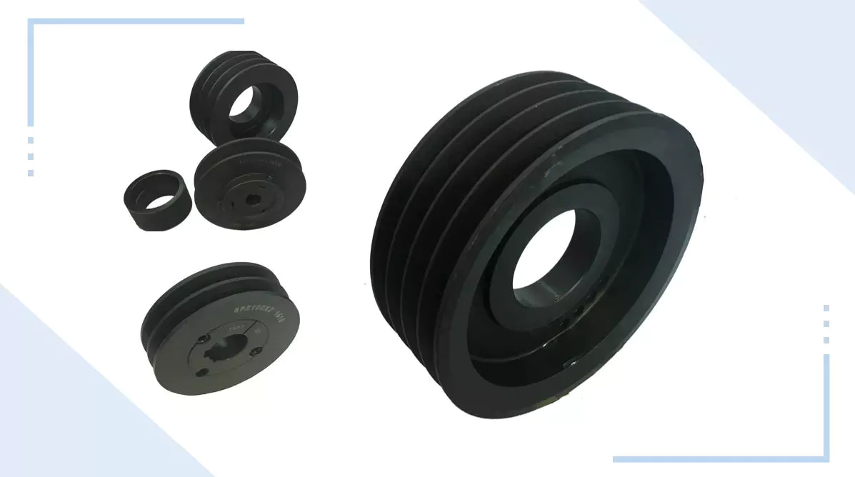
Simple pulley
The simplest theory of operation of a pulley system assumes that the rope and weight are weightless and that the rope and pulley are not stretched. Since the force on the pulley is the same, the force on the pulley shaft must also be zero. Therefore, the force exerted on the pulley shaft is also distributed evenly between the 2 wires passing through the pulley. The force distribution is shown in Figure 1.
The use of simple pulleys is as old as history. Before the Industrial Revolution, people relied on muscle strength to carry heavy loads. Pulleys, levers and ramps make this possible. Today, we can see pulleys in a variety of systems, from exercise equipment to garage doors, and even rock climbers use them to help them reach greater heights. As you can see, these simple machines have been around for centuries and are used in everyday life.
Another simple pulley system is the pulley system. In this system, there is a fixed pulley at the top and a movable pulley at the bottom. The 2 pulleys are connected by a rope. This combination reduces the amount of work required to lift the load. Additionally, the ropes used in this system are usually made of rope and woven through the individual wheels of the pulley drum.
A pulley is an ingenious device that distributes weight evenly and can be used to lift heavy objects. It is easy to build and can be easily modified for a wide range of activities. Even young children can make their own with very few materials. You can also use simple household items such as washing machines, thin textbooks and even chopsticks. It’s very useful and can be a great addition to your child’s science and engineering activities.
The simplest pulley system is movable. The axis of the movable pulley can move freely in space. The load is attached to 1 end of the pulley and the other end to the stationary object. By applying force on the other end of the rope, the load is lifted. The force at the other end of the rope is equal to the force at the free end of the pulley.
Another form of pulley is the compound pulley. Compound pulleys use 2 or more wheels to transmit force. Compound pulleys have 2 or more wheels and can lift heavier objects. Dim is POLE2.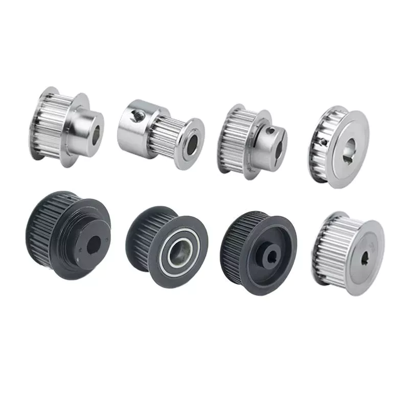
tapered pulley
It is important to clean and align the bolt holes before assembling the tapered pulley. The screws should be lubricated and the threads cleaned before installation. To install the pulley, insert it into the shaft keyway. The keyway should be aligned with the shaft hole to prevent foreign matter from entering the pulley. Then, alternately tighten the bolts until the pulley is tightened to the desired torque.
A tapered pulley is a basic structure. The pulley belt is arranged across 4 steps. Installed between the headstock casting and the main shaft, it is often used in the paper industry. It integrates with printing machinery and supports assembly lines. These pulleys are also available in metric range options, eliminating the need for ke-waying or re-drilling. They are easy to install, and users can even customize them to suit their needs.
CZPT Private Limited is a company that provides unique products for various industries. This large product is used for many different purposes. Also, it is manufactured for industrial use. The company’s website provides detailed specifications for the product. If you need a tapered pulley, contact a company in your area today to purchase a quality product!
Tapered pulleys are vital to paper mill machinery. Its special design and construction enable it to transmit power from the engine source to the drive components. The advantages of this pulley include low maintenance costs and high mechanical strength. Cone wheel diameters range from 10 inches to 74 inches. These pulleys are commonly used in paper mills as they offer low maintenance, high mechanical strength and low wear.
A tapered sleeve connects the pulley to the shaft and forms an interference fit connector. The taper sleeve is fixed on the shaft with a key, and the corresponding inner hole is fixed on the shaft with a key. These features transmit torque and force to the pulley through friction. This allows the tapered pulley to move in a circular motion. The torque transfer characteristics of this pulley are most effective in high speed applications.
The sleeve is the most important part when assembling the tapered pulley. There is an 8-degree taper inside the cone, which is closely connected to the inner surface of the pulley. Taper sleeves and pulleys are interchangeable. However, tapered pulleys can be damaged after prolonged use.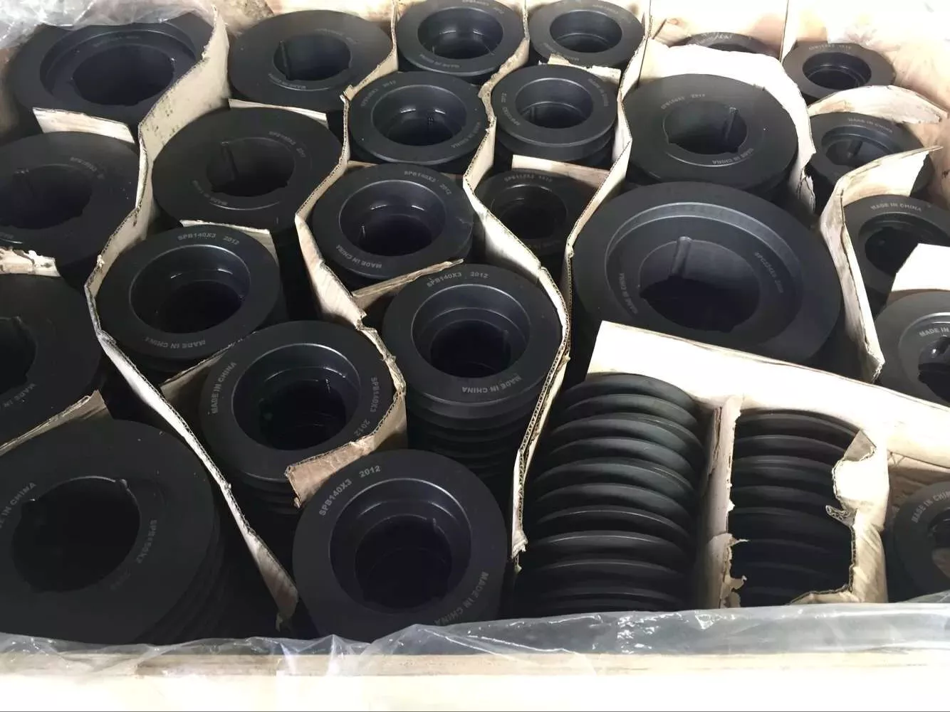
pulley pulley system
A pulley pulley system is a great way to move heavy objects. These systems have been around for centuries, dating back to the ancient Greeks. This simple mechanism enables a person to lift heavy objects. These blocks are usually made of rope, and the number of turns varies for different types of rope. Some blocks have more cords than others, which creates friction and interferes with the easy movement of the lifting system.
When using a pulley pulley, the first thing to decide is which direction to pull. Unfavorable rigging means pulling in the opposite direction. In theory, this method is less efficient, but sometimes requires a certain amount of work space. The benefit is that you will increase the mechanical advantage of the pulley by pulling in the opposite direction. So the interception and tackle system will give you more of a mechanical advantage.
Pulley pulleys are an excellent choice for lifting heavy objects. The system is simple to install and users can easily lift objects without extensive training. Figure 3.40 shows a pulley in action. In this photo, the person on the left is pulling a rope and tying the end of the rope to a weight. When the rope is attached to the load, the rope will be pulled over the pulley and pulley.
The blocks on the blocks are attached to the ends of the rope. This creates unique lifting advantages compared to single-line systems. In Figure 3, the 10sion of each thread is equal to 1-third of the unit weight. When the rope is pulled over the pulley, the force is divided equally between the 2 wires. The other pulley reverses the direction of the force, but that doesn’t add any advantage.
Use pulleys to reduce traction and load. The weight of the load has not changed, but the length of the rope has increased. Using this method, lifting the load by pulling the rope 4 times reduces the force required to lift 1 foot. Likewise, if the pulley system had 4 pulleys instead of 3, the length of the rope would be tripled.
The system can transmit loads in any direction. Rope length is determined by multiplying the distance from the fixed block to the load by the mechanical advantage. If the mechanical advantage is 3:1, then passing the rope through the pulley 3 times will produce the required traction distance. Also, the length of the rope will depend on the mechanical advantage, so if the load is 3 times the length of the rope, it will be more than 3 times the required length.