Description
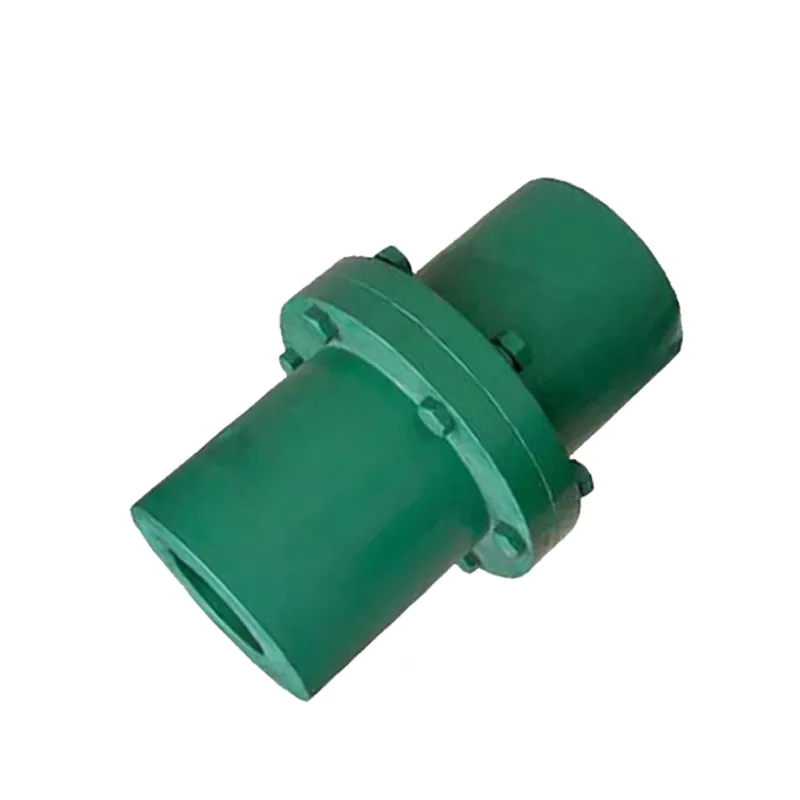
GY2/GYS2/GYH2 Flanged Coupling – 16–25mm Bore Rigid Flange Coupling to GB/T 5843-2003
The GY2/GYS2/GYH2 type flanged coupling is the most widely used rigid coupling for cylindrical shaft connections in industrial machinery — conforming to Chinese national standard GB/T 5843-2003. Three structural subtypes are available within each model number: GY type, which uses a hinge bolt hole system allowing assembly and disassembly without moving the coupling along the axial direction; GYS type, which adds a precision alignment boss (凸楔) at the flange mating face to ensure accurate shaft concentricity on reassembly without realignment measurement; and GYH type, which uses a ring (sleeve) design that assembles and disassembles by axial movement. All three subtypes share the same outer diameter (90 mm), bore range (16–25 mm), nominal torque (63 N·m), and maximum speed (10000 rpm). The GY2/GYS2/GYH2 group serves 16–25 mm shaft connections at 10000 rpm, covering IEC frame 71 and 80 motor output shaft sizes. At 63 N·m rated torque, the group covers a broad range of small industrial drive connections. The GYS2 type with alignment boss is particularly used on printing machine and textile equipment drives where frequent maintenance disconnection without realignment is valued.
The coupling transmits torque through a bolted flange joint — each hub mounts on one shaft via keyway and key, and the two hub flanges are bolted together with reamed-hole precision bolts. This provides a rigid, zero-backlash connection with no flexible elements. The GY-type hinge bolt design allows the coupling to be disconnected by removing the flange bolts without requiring either shaft to move axially — a significant maintenance advantage over sleeve couplings. The GYS-type alignment boss further improves maintenance efficiency by ensuring the two hub halves re-centre precisely on reconnection, eliminating the need for dial indicator verification after each coupling reconnection in planned maintenance schedules.
Shaft hole dimensions and keyway forms comply with GB3852-1997. Both Y-type and J-type bores are available; tapered bores are also available. The complete GY/GYS/GYH coupling series is listed on our product catalog page.
Technical Specifications
| Parameter | Value |
|---|---|
| Model Numbers | GY2, GYS2, GYH2 |
| Standard | GB/T 5843-2003 |
| Bore Range (d1, d2) | 16–25 mm |
| Outer Diameter (D) | 90 mm |
| Flange Boss Width (b) | 28 mm |
| Ring Width (b1, GYH) | 44 mm |
| Face Gap (S) | 6 mm |
| Nominal Torque (Tn) | 63 N·m |
| Maximum Speed [n] | 10000 rpm |
| Rotational Inertia | 0.0015 kg·m² |
| Mass (approx.) | 1.72 kg |
| Material | Cast Iron (HT200) standard; cast steel available |
| Bore Type | Y-type, J-type, or tapered bore |
GY, GYS and GYH Subtype Dimension Reference
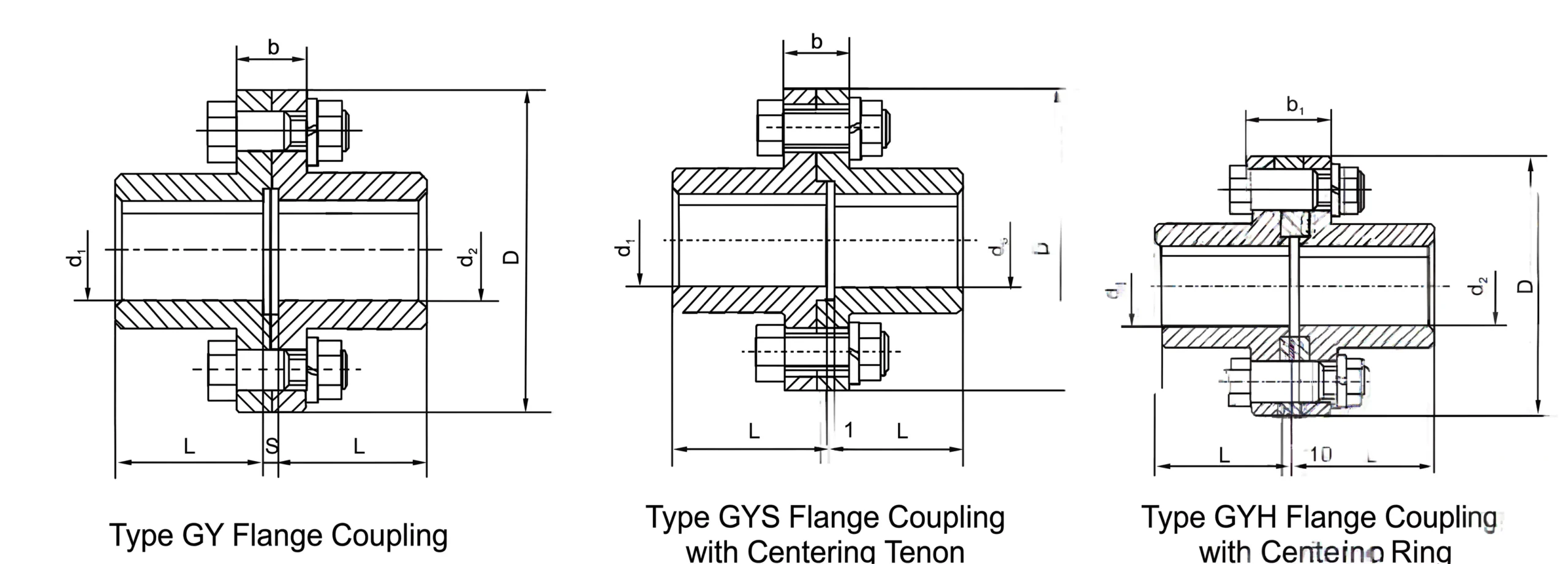
Three Subtype Comparison
GY Type – Hinge Bolt
The standard GY type uses a hinge bolt hole system. Assembly and disassembly are performed by removing the flange bolts — no axial shaft movement required. This is the simplest GY subtype and is specified when maintenance reconnection frequency is low or when realignment is acceptable.
GYS Type – Alignment Boss
GYS type adds a precision alignment boss (凸楔) at the flange mating face. When reassembled after maintenance, the boss centres the two hub halves concentrically, eliminating realignment measurement. Specified where frequent planned maintenance disconnection is required and realignment time must be minimised.
GYH Type – Ring Design
GYH type uses a ring (sleeve) structural element and assembles by axial movement along the shaft. This method suits installations where the coupling geometry requires axial assembly access. Processing convenience is noted as a feature; disassembly also moves along the axial direction.
Zero Backlash – All Subtypes
All three GY subtypes transmit torque through rigid bolted flange joints and key-keyway shaft connections — providing absolute zero backlash. The rated 63 N·m and 10000 rpm apply equally to GY, GYS, and GYH configurations.
Manufacturing Quality
Typical Applications
- Pump motor shaft connections — GYS type for frequent maintenance disconnection without realignment
- Industrial fan and blower drive connections — rigid flanged coupling for motor-to-shaft zero-backlash connection
- Chemical mixing and agitator drive connections — flanged coupling with subtype options for installation flexibility
- Conveyor head drive shaft connections — sustained duty rigid flanged coupling with maintenance disconnection
For volume supply and custom bore configurations, visit our contact page.
Customer Reviews and Case Studies
★★★★★
United Kingdom — Printing Machine OEM
GY2, GYS2, and GYH2 type flanged couplings are used throughout our web printing press product range. The GYS type’s alignment tenon ensures accurate shaft concentricity on reconnection after maintenance — critical for print registration accuracy on our high-precision presses.
— Lead Engineer, Leeds
★★★★★
France — Textile Machinery OEM
We use GY2 type couplings on roll drive shaft connections in our textile machinery range. The rigid flanged connection maintains accurate phase between roll drive sections and the hinge bolt allows roll disconnection without disturbing the bearing housing.
— Design Engineer, Lyon
★★★★☆
Canada — Packaging Equipment
GY2 and GYS2 couplings installed on packaging machine drive connections. The 10,000 rpm rating covers our highest-speed packaging operations and the flange joint allows motor removal between packaging format changes.
— Equipment Engineer, Toronto
Frequently Asked Questions
How does the GYS type alignment boss work?
The GYS type flanged coupling incorporates a precision-machined male protrusion (boss) on one flange face and a matching recess on the opposite flange. When the coupling is assembled, the boss fits into the recess and centres the two flanges concentrically. This ensures accurate shaft alignment on reassembly after maintenance without dial indicator measurement — equivalent to the YLD type alignment tenon but in the GY coupling family.
How does the GYH type assembly differ from GY and GYS?
The GYH type (ring type) uses a sleeve or ring that surrounds the flange connection, and assembly and disassembly require movement along the axial direction. This differs from the GY type which uses hinge bolts allowing disconnection without axial movement. GYH may be preferred where the axial assembly method suits the installation geometry or where the ring provides additional structural integrity.
What material are GY/GYS/GYH hubs made from?
The standard GY/GYS/GYH coupling hubs are manufactured from cast iron (HT200) for standard applications. Cast steel versions provide higher structural integrity for higher torque or shock load applications. The mass and rotational inertia values in the specification table are calculated for the GY/J type bore configuration at the minimum shaft bore diameter.
What is the significance of b and b1 dimensions in the GY coupling?
Dimension b is the width of the flange boss or pilot diameter feature on the coupling hub face. Dimension b1 is a related dimension on the GYH type ring. These dimensions define the flange geometry and determine the bolt engagement depth and flange rigidity. They are specified in the dimension table for each model size and should be used when designing guards, housing features, or mating components.
What is the S dimension in the GY coupling specification?
S is the gap dimension between the two hub flange faces when the coupling is assembled. It represents the small clearance maintained between the faces to ensure the torque is transmitted through the flange bolts rather than face contact. The standard S value for GY1-GY7 is 6 mm; for GY8-GY12 it is 8-12 mm.
Source GY2/GYS2/GYH2 Flanged Couplings
Ever Power manufactures GY, GYS, and GYH type flanged couplings from GY1 to GY12 per GB/T 5843-2003, direct from our factory. Specify subtype (GY/GYS/GYH), bore sizes, bore type (Y/J/tapered), and material for a prompt technical and commercial response.