Category Archives: rigid shaft coupling

China Good quality High Precision CNC Machining Turning Milling Joint CZPT with high quality

Product Description

High precision CNC machining turning milling joint coupling

We believe that quality goes far over and above a technique

   Muyang equipment is a manufacturer with the ability of comprehensive services of casting, forging and machining, dedicated to the production of personalized components. Since proven in 2002 (former Miaosen Machinery Co., Ltd), we have been providing to the international market for more than fifteen years, served industries consist of automotive, railway, gas and oil, medical equipment, building equipment, gym tools, etc.


We guarantee our clients careful, safe and tight package for exporting!

Regular packing: pearl cotton/bubble bag + carton box + pallet/picket box

Unique packingcustom packaging + wooden box

FAQ:

one. Are you a producer or trading company?
We are a producer with self-export legal rights. 

2. What’s your major enterprise?
Our principal enterprise is custom steel components processed by CNC machining, casting, forging and many others., served industries including railway, auto, bike, construction machinery, gymnasium equipment, water gasoline and oil.

three. Immediately get to Speak to or send out your item drawing/inquiries to e-mail, we will reply within .5 hour.


Capability

CNC machining center –

MAX size: 600*1200*500mm

General tolerance: ±0.005mm

Machine qty: 6 sets     

CNC Milling –

MAX size: 1200*500mm

General tolerance: ±0.02mm

Machine qty: 12 sets        

CNC turning –

MAX size: φ0.5-φ800*1000mm

General tolerance: ±0.005mm

Machine qty: 35 sets       

Robortic Aarm and automated CNC: 7 sets

* Due to the development of the factory, the number of equipment is increasing. If you need to review, we can provide the equipment list  

Service:

CNC turning, CNC milling, CNC grinding, CNC lathe machining, CNC boring, CNC drilling, CNC tapping, surface treatment etc.

Material available

Stainless steel: SS201, SSS301, SS303, SS304, SS316, SS416, SS440C etc.

Steel: Mild steel, Carbon steel, 4140, 4340, Q235, Q345B, 20#, 45#

Brass/Bronze: HPb63, HPb62, HPb61, HPb59, H59, H68, H80, H90, C360, C260, C932

Copper: C11000, C12000, C36000

Aluminum: AL2017, AL2024, AL5052, AL5083, AL6061, AL6063, AL6082, AL7075

Iron: A36, 45#, 1213, 1214, 1215

Others per customers requirements

Surface finish

Aluminum alloy: Clear anodized, color anodized, sand blast anodized, hard anodized, brushing, polishing, powder coated and painting

Brass/copper/steel: Nickel plating, chrome plating

Steel/Stainless steel: Zinc plating, oxide black, carburized, heat treatment, nitriding

Measuring tools

Micrometer, calipers, thread tools, high guage, trapezoidal thread plug gauge, sclerometer, dial indicator, projector

Guide to Drive Shafts and U-Joints

If you’re concerned about the performance of your car’s driveshaft, you’re not alone. Many car owners are unaware of the warning signs of a failed driveshaft, but knowing what to look for can help you avoid costly repairs. Here is a brief guide on drive shafts, U-joints and maintenance intervals. Listed below are key points to consider before replacing a vehicle driveshaft.
air-compressor

Symptoms of Driveshaft Failure

Identifying a faulty driveshaft is easy if you’ve ever heard a strange noise from under your car. These sounds are caused by worn U-joints and bearings supporting the drive shaft. When they fail, the drive shafts stop rotating properly, creating a clanking or squeaking sound. When this happens, you may hear noise from the side of the steering wheel or floor.
In addition to noise, a faulty driveshaft can cause your car to swerve in tight corners. It can also lead to suspended bindings that limit overall control. Therefore, you should have these symptoms checked by a mechanic as soon as you notice them. If you notice any of the symptoms above, your next step should be to tow your vehicle to a mechanic. To avoid extra trouble, make sure you’ve taken precautions by checking your car’s oil level.
In addition to these symptoms, you should also look for any noise from the drive shaft. The first thing to look for is the squeak. This was caused by severe damage to the U-joint attached to the drive shaft. In addition to noise, you should also look for rust on the bearing cap seals. In extreme cases, your car can even shudder when accelerating.
Vibration while driving can be an early warning sign of a driveshaft failure. Vibration can be due to worn bushings, stuck sliding yokes, or even springs or bent yokes. Excessive torque can be caused by a worn center bearing or a damaged U-joint. The vehicle may make unusual noises in the chassis system.
If you notice these signs, it’s time to take your car to a mechanic. You should check regularly, especially heavy vehicles. If you’re not sure what’s causing the noise, check your car’s transmission, engine, and rear differential. If you suspect that a driveshaft needs to be replaced, a certified mechanic can replace the driveshaft in your car.
air-compressor

Drive shaft type

Driveshafts are used in many different types of vehicles. These include four-wheel drive, front-engine rear-wheel drive, motorcycles and boats. Each type of drive shaft has its own purpose. Below is an overview of the three most common types of drive shafts:
The driveshaft is a circular, elongated shaft that transmits torque from the engine to the wheels. Drive shafts often contain many joints to compensate for changes in length or angle. Some drive shafts also include connecting shafts and internal constant velocity joints. Some also include torsional dampers, spline joints, and even prismatic joints. The most important thing about the driveshaft is that it plays a vital role in transmitting torque from the engine to the wheels.
The drive shaft needs to be both light and strong to move torque. While steel is the most commonly used material for automotive driveshafts, other materials such as aluminum, composites, and carbon fiber are also commonly used. It all depends on the purpose and size of the vehicle. Precision Manufacturing is a good source for OEM products and OEM driveshafts. So when you’re looking for a new driveshaft, keep these factors in mind when buying.
Cardan joints are another common drive shaft. A universal joint, also known as a U-joint, is a flexible coupling that allows one shaft to drive the other at an angle. This type of drive shaft allows power to be transmitted while the angle of the other shaft is constantly changing. While a gimbal is a good option, it’s not a perfect solution for all applications.
CZPT, Inc. has state-of-the-art machinery to service all types of drive shafts, from small cars to race cars. They serve a variety of needs, including racing, industry and agriculture. Whether you need a new drive shaft or a simple adjustment, the staff at CZPT can meet all your needs. You’ll be back on the road soon!

U-joint

If your car yoke or u-joint shows signs of wear, it’s time to replace them. The easiest way to replace them is to follow the steps below. Use a large flathead screwdriver to test. If you feel any movement, the U-joint is faulty. Also, inspect the bearing caps for damage or rust. If you can’t find the u-joint wrench, try checking with a flashlight.
When inspecting U-joints, make sure they are properly lubricated and lubricated. If the joint is dry or poorly lubricated, it can quickly fail and cause your car to squeak while driving. Another sign that a joint is about to fail is a sudden, excessive whine. Check your u-joints every year or so to make sure they are in proper working order.
Whether your u-joint is sealed or lubricated will depend on the make and model of your vehicle. When your vehicle is off-road, you need to install lubricable U-joints for durability and longevity. A new driveshaft or derailleur will cost more than a U-joint. Also, if you don’t have a good understanding of how to replace them, you may need to do some transmission work on your vehicle.
When replacing the U-joint on the drive shaft, be sure to choose an OEM replacement whenever possible. While you can easily repair or replace the original head, if the u-joint is not lubricated, you may need to replace it. A damaged gimbal joint can cause problems with your car’s transmission or other critical components. Replacing your car’s U-joint early can ensure its long-term performance.
Another option is to use two CV joints on the drive shaft. Using multiple CV joints on the drive shaft helps you in situations where alignment is difficult or operating angles do not match. This type of driveshaft joint is more expensive and complex than a U-joint. The disadvantages of using multiple CV joints are additional length, weight, and reduced operating angle. There are many reasons to use a U-joint on a drive shaft.
air-compressor

maintenance interval

Checking U-joints and slip joints is a critical part of routine maintenance. Most vehicles are equipped with lube fittings on the driveshaft slip joint, which should be checked and lubricated at every oil change. CZPT technicians are well-versed in axles and can easily identify a bad U-joint based on the sound of acceleration or shifting. If not repaired properly, the drive shaft can fall off, requiring expensive repairs.
Oil filters and oil changes are other parts of a vehicle’s mechanical system. To prevent rust, the oil in these parts must be replaced. The same goes for transmission. Your vehicle’s driveshaft should be inspected at least every 60,000 miles. The vehicle’s transmission and clutch should also be checked for wear. Other components that should be checked include PCV valves, oil lines and connections, spark plugs, tire bearings, steering gearboxes and brakes.
If your vehicle has a manual transmission, it is best to have it serviced by CZPT’s East Lexington experts. These services should be performed every two to four years or every 24,000 miles. For best results, refer to the owner’s manual for recommended maintenance intervals. CZPT technicians are experienced in axles and differentials. Regular maintenance of your drivetrain will keep it in good working order.

China NM Couplings

NM Couplings


Why Checking the Drive Shaft is Important

If you hear clicking noises while driving, your driveshaft may need repair. An experienced mechanic can tell if the noise is coming from 1 side or both sides. This problem is usually related to the torque converter. Read on to learn why it’s so important to have your driveshaft inspected by an auto mechanic. Here are some symptoms to look for. Clicking noises can be caused by many different things. You should first check if the noise is coming from the front or the rear of the vehicle.
air-compressor

hollow drive shaft

Hollow driveshafts have many benefits. They are light and reduce the overall weight of the vehicle. The largest manufacturer of these components in the world is CZPT. They also offer lightweight solutions for various applications, such as high-performance axles. CZPT driveshafts are manufactured using state-of-the-art technology. They offer excellent quality at competitive prices.
The inner diameter of the hollow shaft reduces the magnitude of the internal forces, thereby reducing the amount of torque transmitted. Unlike solid shafts, hollow shafts are getting stronger. The material inside the hollow shaft is slightly lighter, which further reduces its weight and overall torque. However, this also increases its drag at high speeds. This means that in many applications hollow driveshafts are not as efficient as solid driveshafts.
A conventional hollow drive shaft consists of a first rod 14 and a second rod 14 on both sides. The first rod is connected with the second rod, and the second rod extends in the rotation direction. The 2 rods are then friction welded to the central area of ​​the hollow shaft. The frictional heat generated during the relative rotation helps to connect the 2 parts. Hollow drive shafts can be used in internal combustion engines and environmentally-friendly vehicles.
The main advantage of a hollow driveshaft is weight reduction. The splines of the hollow drive shaft can be designed to be smaller than the outside diameter of the hollow shaft, which can significantly reduce weight. Hollow shafts are also less likely to jam compared to solid shafts. Hollow driveshafts are expected to eventually occupy the world market for automotive driveshafts. Its advantages include fuel efficiency and greater flexibility compared to solid prop shafts.

Cardan shaft

Cardan shafts are a popular choice in industrial machinery. They are used to transmit power from 1 machine to another and are available in a variety of sizes and shapes. They are available in a variety of materials, including steel, copper, and aluminum. If you plan to install 1 of these shafts, it is important to know the different types of Cardan shafts available. To find the best option, browse the catalog.
Telescopic or “Cardan” prop shafts, also known as U-joints, are ideal for efficient torque transfer between the drive and output system. They are efficient, lightweight, and energy-efficient. They employ advanced methods, including finite element modeling (FEM), to ensure maximum performance, weight, and efficiency. Additionally, the Cardan shaft has an adjustable length for easy repositioning.
Another popular choice for driveshafts is the Cardan shaft, also known as a driveshaft. The purpose of the driveshaft is to transfer torque from the engine to the wheels. They are typically used in high-performance car engines. Some types are made of brass, iron, or steel and have unique surface designs. Cardan shafts are available in inclined and parallel configurations.
Single Cardan shafts are a common replacement for standard Cardan shafts, but if you are looking for dual Cardan shafts for your vehicle, you will want to choose the 1310 series. This type is great for lifted jeeps and requires a CV-compatible transfer case. Some even require axle spacers. The dual Cardan shafts are also designed for lifts, which means it’s a good choice for raising and lowering jeeps.
air-compressor

universal joint

Cardan joints are a good choice for drive shafts when operating at a constant speed. Their design allows a constant angular velocity ratio between the input and output shafts. Depending on the application, the recommended speed limit may vary depending on the operating angle, transmission power, and application. These recommendations must be based on pressure. The maximum permissible speed of the drive shaft is determined by determining the angular acceleration.
Because gimbal joints don’t require grease, they can last a long time but eventually fail. If they are poorly lubricated or dry, they can cause metal-to-metal contact. The same is true for U-joints that do not have oil filling capability. While they have a long lifespan, it can be difficult to spot warning signs that could indicate impending joint failure. To avoid this, check the drive shaft regularly.
U-joints should not exceed 7ty percent of their lateral critical velocity. However, if this speed is exceeded, the part will experience unacceptable vibration, reducing its useful life. To determine the best U-joint for your application, please contact your universal joint supplier. Typically, lower speeds do not require balancing. In these cases, you should consider using a larger pitch diameter to reduce axial force.
To minimize the angular velocity and torque of the output shaft, the 2 joints must be in phase. Therefore, the output shaft angular displacement does not completely follow the input shaft. Instead, it will lead or lag. Figure 3 illustrates the angular velocity variation and peak displacement lead of the gimbal. The ratios are shown below. The correct torque for this application is 1360 in-Ibs.

Refurbished drive shaft

Refurbished driveshafts are a good choice for a number of reasons. They are cheaper than brand new alternatives and generally just as reliable. Driveshafts are essential to the function of any car, truck, or bus. These parts are made of hollow metal tubes. While this helps reduce weight and expense, it is vulnerable to external influences. If this happens, it may crack or bend. If the shaft suffers this type of damage, it can cause serious damage to the transmission.
A car’s driveshaft is a critical component that transmits torque from the engine to the wheels. A1 Drive Shaft is a global supplier of automotive driveshafts and related components. Their factory has the capability to refurbish and repair almost any make or model of driveshafts. Refurbished driveshafts are available for every make and model of vehicle. They can be found on the market for a variety of vehicles, including passenger cars, trucks, vans, and SUVs.
Unusual noises indicate that your driveshaft needs to be replaced. Worn U-joints and bushings can cause excessive vibration. These components cause wear on other parts of the drivetrain. If you notice any of these symptoms, please take your vehicle to the AAMCO Bay Area Center for a thorough inspection. If you suspect damage to the driveshaft, don’t wait another minute – it can be very dangerous.
air-compressor

The cost of replacing the drive shaft

The cost of replacing a driveshaft varies, but on average, this repair costs between $200 and $1,500. While this price may vary by vehicle, the cost of parts and labor is generally equal. If you do the repair yourself, you should know how much the parts and labor will cost before you start work. Some parts can be more expensive than others, so it’s a good idea to compare the cost of several locations before deciding where to go.
If you notice any of these symptoms, you should seek a repair shop immediately. If you are still not sure if the driveshaft is damaged, do not drive the car any distance until it is repaired. Symptoms to look for include lack of power, difficulty moving the car, squeaking, clanking, or vibrating when the vehicle is moving.
Parts used in drive shafts include center support bearings, slip joints, and U-joints. The price of the driveshaft varies by vehicle and may vary by model of the same year. Also, different types of driveshafts require different repair methods and are much more expensive. Overall, though, a driveshaft replacement costs between $300 and $1,300. The process may take about an hour, depending on the vehicle model.
Several factors can lead to the need to replace the drive shaft, including bearing corrosion, damaged seals, or other components. In some cases, the U-joint indicates that the drive shaft needs to be replaced. Even if the bearings and u-joints are in good condition, they will eventually break and require the replacement of the drive shaft. However, these parts are not cheap, and if a damaged driveshaft is a symptom of a bigger problem, you should take the time to replace the shaft.

China Jaw Couplings

Jaw Couplings

How to Assemble a Pulley System

A pulley is a wheel that rotates on a shaft or shaft to support the movement of a taut cable. Pulleys allow power to be transmitted from the shaft to the cable.
pulley

Simple pulley

The simplest theory of operation of a pulley system assumes that the rope and weight are weightless and that the rope and pulley are not stretched. Since the force on the pulley is the same, the force on the pulley shaft must also be zero. Therefore, the force exerted on the pulley shaft is also distributed evenly between the 2 wires passing through the pulley. The force distribution is shown in Figure 1.
The use of simple pulleys is as old as history. Before the Industrial Revolution, people relied on muscle strength to carry heavy loads. Pulleys, levers and ramps make this possible. Today, we can see pulleys in a variety of systems, from exercise equipment to garage doors, and even rock climbers use them to help them reach greater heights. As you can see, these simple machines have been around for centuries and are used in everyday life.
Another simple pulley system is the pulley system. In this system, there is a fixed pulley at the top and a movable pulley at the bottom. The 2 pulleys are connected by a rope. This combination reduces the amount of work required to lift the load. Additionally, the ropes used in this system are usually made of rope and woven through the individual wheels of the pulley drum.
A pulley is an ingenious device that distributes weight evenly and can be used to lift heavy objects. It is easy to build and can be easily modified for a wide range of activities. Even young children can make their own with very few materials. You can also use simple household items such as washing machines, thin textbooks and even chopsticks. It’s very useful and can be a great addition to your child’s science and engineering activities.
The simplest pulley system is movable. The axis of the movable pulley can move freely in space. The load is attached to 1 end of the pulley and the other end to the stationary object. By applying force on the other end of the rope, the load is lifted. The force at the other end of the rope is equal to the force at the free end of the pulley.
Another form of pulley is the compound pulley. Compound pulleys use 2 or more wheels to transmit force. Compound pulleys have 2 or more wheels and can lift heavier objects. Dim is POLE2.
pulley

tapered pulley

It is important to clean and align the bolt holes before assembling the tapered pulley. The screws should be lubricated and the threads cleaned before installation. To install the pulley, insert it into the shaft keyway. The keyway should be aligned with the shaft hole to prevent foreign matter from entering the pulley. Then, alternately tighten the bolts until the pulley is tightened to the desired torque.
A tapered pulley is a basic structure. The pulley belt is arranged across 4 steps. Installed between the headstock casting and the main shaft, it is often used in the paper industry. It integrates with printing machinery and supports assembly lines. These pulleys are also available in metric range options, eliminating the need for ke-waying or re-drilling. They are easy to install, and users can even customize them to suit their needs.
CZPT Private Limited is a company that provides unique products for various industries. This large product is used for many different purposes. Also, it is manufactured for industrial use. The company’s website provides detailed specifications for the product. If you need a tapered pulley, contact a company in your area today to purchase a quality product!
Tapered pulleys are vital to paper mill machinery. Its special design and construction enable it to transmit power from the engine source to the drive components. The advantages of this pulley include low maintenance costs and high mechanical strength. Cone wheel diameters range from 10 inches to 74 inches. These pulleys are commonly used in paper mills as they offer low maintenance, high mechanical strength and low wear.
A tapered sleeve connects the pulley to the shaft and forms an interference fit connector. The taper sleeve is fixed on the shaft with a key, and the corresponding inner hole is fixed on the shaft with a key. These features transmit torque and force to the pulley through friction. This allows the tapered pulley to move in a circular motion. The torque transfer characteristics of this pulley are most effective in high speed applications.
The sleeve is the most important part when assembling the tapered pulley. There is an 8-degree taper inside the cone, which is closely connected to the inner surface of the pulley. Taper sleeves and pulleys are interchangeable. However, tapered pulleys can be damaged after prolonged use.
pulley

pulley pulley system

A pulley pulley system is a great way to move heavy objects. These systems have been around for centuries, dating back to the ancient Greeks. This simple mechanism enables a person to lift heavy objects. These blocks are usually made of rope, and the number of turns varies for different types of rope. Some blocks have more cords than others, which creates friction and interferes with the easy movement of the lifting system.
When using a pulley pulley, the first thing to decide is which direction to pull. Unfavorable rigging means pulling in the opposite direction. In theory, this method is less efficient, but sometimes requires a certain amount of work space. The benefit is that you will increase the mechanical advantage of the pulley by pulling in the opposite direction. So the interception and tackle system will give you more of a mechanical advantage.
Pulley pulleys are an excellent choice for lifting heavy objects. The system is simple to install and users can easily lift objects without extensive training. Figure 3.40 shows a pulley in action. In this photo, the person on the left is pulling a rope and tying the end of the rope to a weight. When the rope is attached to the load, the rope will be pulled over the pulley and pulley.
The blocks on the blocks are attached to the ends of the rope. This creates unique lifting advantages compared to single-line systems. In Figure 3, the 10sion of each thread is equal to 1-third of the unit weight. When the rope is pulled over the pulley, the force is divided equally between the 2 wires. The other pulley reverses the direction of the force, but that doesn’t add any advantage.
Use pulleys to reduce traction and load. The weight of the load has not changed, but the length of the rope has increased. Using this method, lifting the load by pulling the rope 4 times reduces the force required to lift 1 foot. Likewise, if the pulley system had 4 pulleys instead of 3, the length of the rope would be tripled.
The system can transmit loads in any direction. Rope length is determined by multiplying the distance from the fixed block to the load by the mechanical advantage. If the mechanical advantage is 3:1, then passing the rope through the pulley 3 times will produce the required traction distance. Also, the length of the rope will depend on the mechanical advantage, so if the load is 3 times the length of the rope, it will be more than 3 times the required length.

China wholesaler Shear Bolt Torque Limiter SB Series for PTO Drive Shafts with Best Sales

Shear Bolt Torque Limiter SB Series for PTO Drive Shafts

The shear bolt torque limiter SB series of Ever-Power Transmission is a device that interrupts power transmission when the transmitted torque exceeds a set value.
This power interruption is caused by the shearing of the bolt. This bolt must be replaced before power can be restored.
The use of a shear bolt torque limiter is recommended to avoid damage to the drive system of a machine mounted on a machine subjected to unexpected overloads or torque peaks.

The torque setting of the shear bolt torque limiter is usually double or triple the intermediate torque M and must not exceed the maximum torque of the drive train. The standard settings for each size SFT driveline are shown in the table to the right. SB Torque Limiter sizes S1 through S4 have a pinned attachment to the spline shaft. Larger sizes use a tapered pin attachment.

Note: For operator safety and reliable driveline function, replace only 1 bolt of the same length, diameter, and grade as the original.

Specification of Shear Bolt Torque Limiter

  1. Yoke
  2. Grease nipple
  3. Steel ball
  4. Hub
  5. Push pin
  6. Shear bolt & Nut
  1. Yoke
  2. Grease nipple
  3. Steel ball
  4. Hub
  5. Push pin (Qty.=2)
  6. Shear bolt & Nut

Advantages of Shear Bolt Torque Limiter 

One of the biggest advantages of PTO shear bolt torque limiters is that they protect against overload. They work in a similar way to a 1:1 transmission when the torque is less than a predetermined value. Once the torque exceeds the limit, the limiter acts as a clutch and removes inertial energy from the drive train. They operate in milliseconds, making them suitable for a wide range of applications, including conveyors, assembly lines, textile machinery, and printing machines.

This torque limiter is usually made from hardened steel and is backlash-free. It features additional springs for adjusting the limit. It is available in several models, including pneumatic, hydraulic, and mechanical. It can be installed in a variety of positions, depending on the torque limiter’s purpose. During normal use, it does not need to be adjusted. During a malfunction, the user can simply disconnect the auger to restore PTO functionality.

One of the advantages of the shear bolt torque limiters for PTO tractor drive shaft is that they don’t waste any energy, allowing you to tow the vehicle. Without this technology, towing would be impossible. Besides, a PTO shear bolt torque limiter is more durable than a manual limiter.

Another major benefit of a PTO shear bolt torque limiter is that it offers a safety measure if a PTO-driven implement jams. A small farm tractor can give up when running at 3800 RPM, and if it suddenly stops, the PTO shaft can also fail. The torque limiting device is the first line of defense against such catastrophic failures, and this slip clutch device eliminates the need to change pins.

Agricultural Gearbox and PTO Shaft

Agricultural gearbox and PTO shaft: These components work together to transfer mechanical power between farm tractors. A PTO shaft converts engine energy into hydraulic pressure. This is what allows the tractor to pull heavy loads. When properly functioning, it reduces the risk of damage to the tractor and to the operator. When used properly, it is an important component of a tractor, but it can also become defective. When choosing an agricultural gearbox, consider the durability and mechanism of the product, as well as its materials. A durable gearbox will last for many years, avoiding repeated replacements. A high-quality agricultural gearbox will be durable for many years to come, and you don’t want to end up replacing it for a while. This can be costly, so consider your needs when purchasing an agricultural gearbox and PTO shaft.

Additional information

Edited

Zqq

China wholesaler Agricultural spare parts end cover near me supplier

Tractors, excavators, and other industrial engines have agricultural spare components conclude protect. These replacement parts are entirely assured, and several components even have a twelve-month warranty period of time. All elements are totally guaranteed. Below are some valuable guidelines to locate suitable substitution components for your machine. You will be satisfied. In addition, please bear in mind to verify the guarantee of any areas acquired from approved sellers. In this way, you will not have to fear about missing some key factors.
Description of cell agricultural tools
The definition of cellular agricultural gear contains products employed in agriculture, forestry, building, and irrigation. It also consists of equipment and spare areas conclude include. As the benefit of cellular agricultural products raises, it is important to make sure that the insurance policies plan provides proper coverage. As a result, the insurance policies policy must be carefully reviewed. Listed here are some items you want to locate in the insurance plan. You will find that the definition of cellular agricultural equipment is various from industrial automobiles, farm legal responsibility, or other kinds of insurance policies.
The description of the conclude cover of mobile agricultural gear need to offer adequate coverage. Normal will protect glass Hurt and specified lead to of decline. The insurance does not cover digital equipment, except gear permanently installed in machinery. This consists of units that transmit audio and video clip alerts or duplicate knowledge. In addition, it will not consist of the cost of changing digital gear in the celebration of a catastrophic incident. The go over plate must also provide satisfactory ventilation for employees functioning in close proximity to the tools during darkness.
Substitutes for unique components of industrial engines
If you possess an agricultural motor, you could locate a higher-good quality substitute for it. If you have troubles, there are many very good substitutes for original areas. These factors are developed for agricultural programs and have verified to offer optimum functionality and longevity. Whether you are managing the harvester, baler, or combine, you can ensure that the replaced elements will also operate appropriately.
supplier
If you are seeking for a provider of agricultural spare components stop caps, you have appear to the proper place. The catalog combines the checklist of the biggest agricultural spare elements suppliers with the sort of chatting with agricultural logistics authorities. You can even search the groups on each supplier’s internet site to uncover the elements that fit your requirements. You can also uncover a lot more info about certain varieties of agricultural machinery by clicking on the merchandise they promote.

Related merchandise

We Also Source PTO Shafts &amp Agricultural Gearboxes

If you also require the PTO shafts, simply click here:https://www.ever-electricity.web/pto-drive-shaft/

We Also Supply Agricultural Gearboxes

Company Data

You may possibly need to have gearboxes, hydraulic cylinders or a trailer hitch to get all your machines working and prepared when you start off functioning your fields. We at HZPT will ensure your agricultural wants are satisfied, providing you with gear and parts that are appropriate for your agricultural application. We’re happy to offer more than 6,000 parts in stock, so you can be positive we will have broken parts in require of substitution. No matter whether you want hitch pins, blades, tines, PTO shafts, bale spears, disc bearings, roller chains, Caroni lawn mower components or sprayers. Even treat by yourself to a manufacturer new tractor seat for a more cozy and cozy perform day.

HZPT TRANSMISSION GROP, referred to as HZPT for limited, Hzpt is a subsidiary of ever power,is a Chinese auto and agricultural equipment areas producer, we do not produce agricultural equipment, we create replacement elements for agricultural equipment. We have been set up for more than twenty a long time and have a wealth of expertise and experience. With constant growth, at any time-power team has turn into a globally regarded chief in the automotive and agricultural equipment parts market. At present, our goods are exported all over the globe, like Asia Pacific, South The united states and Europe.

Additional information

Edited

hyw

ep

January 18, 2021

Common Description
Consisting of a pressure balanced gear pump, DC motor, multi-functional manifold, valves, tank, ect., this energy unit is made to operate material dealing with tools. The lowering movement is achived by the solenoid valve together with the lowering velocity managed by an adjustable needle valve. The left and correct functions are outfitted having a dual pilot operated test valve and cross-over relief valves.
Remark: Please consult our product sales engineer for your various pump displacement, motor power or tank capability.
Particular Notes
one. This power unit is of S3 duty cycle, i.e.,non-continuous operation,thirty seconds on and 270 seconds off.
two. Clean the many hydraulic components concerned before installation of the electrical power unit.
three. Viscosity of the hydraulic oil shoud be 15~46 cst, which ought to also be clean and free of impurities.N46 hydraulic oil is encouraged.
four. This energy unit really should be mounted horizontal.
5. Check the oil degree from the tank right after the initial start off on the energy unit.
6. Oil altering is required just after the initial 100 operation hours, afterwards when every single 3000 hours.

ep

January 18, 2021

DUMP TRAILER Electrical power UNIT- SINGLE ACTING
Basic Description
This power unit features a power up gravity down circuit. Begin the motor to lengthen the cylinder and activate the solenoid valve to retract the circuit. Guide override to solenoid valve might be provided if required. Also a pressure compen sated flow control is often extra to your circuit to regulate the descent velocity on the cylinder.
Remark: Please talk to our sales engineer for the distinctive pump displacement, motor energy or tank capability.
Specific Notes
1. This power unit is of S3 duty cycle, i.e., non-continuous operation, thirty seconds on and 270 seconds off.
2. Clean all the hydraulic parts concerned prior to installation of the power unit.
3. Viscosity of your hydraulic oil shoud be 15~46 cst,which need to also be clean and free of impurities.N46 hydraulic oil is advisable.
four. The power unit really should be mounted horizontally.
5. Check the oil degree during the tank right after the initial running of your power unit.
6. Oil shifting is required soon after the first one hundred operation hrs, afterwards the moment every 3000 hrs.

DUMP TRAILER Electrical power UNIT-DOUBLE ACTING
Common Description
This electrical power unit features a electrical power up energy down circuit with load holding on both A & B ports. A strain compensatred movement control is usually added to circuit to regulate the decent velocity of your cylinder.
Distinctive Notes
1. This energy unit is of S3 duty cycle, i.e., non-continuous operation, thirty seconds on and 270 seconds off.
2. Clean all the hydraulic parts concerned in advance of installation of the energy unit.
3. Viscosity with the hydraulic oil shoud be 15~46 cst, which really should also be clean and absolutely free of impurities. N46 hydraulic oil is encouraged.
four. The energy unit must be mounted horizontally.
five. Check the oil level while in the tank soon after the original working with the energy unit.
6. Oil shifting is required following the original one hundred operation hours, afterwards the moment every single 3000 hrs.

ep

January 18, 2021

Common Description
Outfitted with the zero leak bidirectional checking sole-noid valves, this electrical power unit is intended for your operation of two independent circuits. Which are respectively for your key and subordinate platforms from the double scissors lift. Two cut-off valves are employed for reducing the machine manually in situation of power reduction. If more independent circuits are required for the application please speak to us for availability.
Remark: one. Please seek advice from our income engineer for your distinctive pump displacement, motor power or tank capability.
2. CSA or UL certified motors are available on request.
Particular Notes
one. The AC motor is of S3 duty cycle, which might only get the job done intermittently and repeatedly, i.e., 1minute on and 9 minutes off.
two. Clean every one of the hydraulic parts concerned prior to set up of the electrical power unit.
three. Viscosity of your oil shoud be 15~46 cst,as well as the oil ought to be clean and no cost of impurities,N46 hydraulic oil is proposed.
four. The electrical power unit should be mounted vertically.
5. Check the oil degree while in the tank soon after the first operating on the power unit.
6. Oil modifying is needed right after the preliminary a hundred operation hrs,afterwards when each 3000 hrs.

ep

January 15, 2021

Introduction
A mindful assessment on the ailments surrounding a conveyor is necessary for accurate conveyor chain variety. This part discusses the fundamental considerations demanded for effective conveyor chain choice. Roller Chains are sometimes employed for light to reasonable duty materials dealing with applications. Environmental conditions may possibly call for using special materials, platings coatings, lubricants or the means to operate without having extra external lubrication.
Basic Details Expected For Chain Assortment
? Type of chain conveyor (unit or bulk) which includes the method of conveyance (attachments, buckets, via rods and so forth).
? Conveyor layout which include sprocket places, inclines (if any) and also the amount of chain strands (N) to become employed.
? Amount of materials (M in lbs/ft or kN/m) and sort of materials to be conveyed.
? Estimated weight of conveyor components (W in lbs/ft or kN/m) such as chain, slats or attachments (if any).
? Linear chain pace (S in ft/min or m/min).
? Environment through which the chain will operate together with temperature, corrosion circumstance, lubrication issue and so forth.
Phase 1: Estimate Chain Tension
Use the formula below to estimate the conveyor Pull (Pest) and after that the chain stress (Check). Pest = (M + W) x f x SF and
Test = Pest / N
f = Coefficient of Friction
SF = Velocity Factor
Stage two: Make a Tentative Chain Choice
Utilizing the Check value, produce a tentative variety by selecting a chain
whose rated operating load higher than the calculated Check value.These values are proper for conveyor support and are diff erent from people shown in tables at the front in the catalog which are associated with slow speed drive chain usage.
Moreover to suffi cient load carrying capacity generally these chains needs to be of a specific pitch to accommodate a preferred attachment spacing. By way of example if slats are to be bolted to an attachment just about every one.five inches, the pitch from the chain chosen ought to divide into one.5?¡À. As a result 1 could use a 40 chain (1/2?¡À pitch) with the attachments every 3rd, a 60 chain (3/4?¡À pitch) using the attachments just about every 2nd, a 120 chain (1-1/2?¡À pitch) with the attachments each pitch or even a C2060H chain (1-1/2?¡À pitch) with the attachments every pitch.
Stage 3: Finalize Selection – Calculate Real Conveyor Pull
After generating a tentative variety we need to verify it by calculating
the actual chain tension (T). To do this we need to fi rst determine the actual conveyor pull (P). From the layouts shown on the appropriate side of this webpage pick out the proper formula and determine the total conveyor pull. Note that some conveyors may very well be a combination of horizontal, inclined and vertical . . . in that case calculate the conveyor Pull at every section and add them with each other.
Phase four: Determine Greatest Chain Stress
The utmost Chain Tension (T) equals the Conveyor Pull (P) as calculated in Step three divided through the amount of strands carrying the load (N), occasions the Speed Issue (SF) proven in Table two, the Multi-Strand Issue (MSF) shown in Table 3 as well as Temperature Element (TF) shown in Table four.
T = (P / N) x MSF x SF x TF
Stage five: Verify the ?¡ãRated Working Load?¡À from the Picked Chain
The ?¡ãRated Operating Load?¡À of the chosen chain must be higher than the Greatest Chain Tension (T) calculated in Step four over. These values are proper for conveyor support and therefore are diff erent from these proven in tables with the front on the catalog that are related to slow speed drive chain utilization.
Step 6: Examine the ?¡ãAllowable Roller Load?¡À from the Chosen Chain
For chains that roll around the chain rollers or on leading roller attachments it can be required to examine the Allowable Roller Load?¡À.
Note: the Roller load is determined by:
Roller Load = Wr / Nr
Wr = The complete bodyweight carried by the rollers
Nr = The amount of rollers supporting the weight.

ep

January 15, 2021

Leaf Chains are made for high load, slow pace stress linkage applications. Generally these are specifi ed for reciprocating movement lifting gadgets such as fork lifts or cranes. These chains are generally supplied to a specifi c length and are connected to a clevis block at every single finish. The clevis may perhaps accommodate male ends (within or occasionally referred to as “articulating” hyperlinks) or female ends (outside or even the backlinks on the pin website link) as expected (see illustration below)
Leaf chains can be found in 3 series; AL (light duty), BL (hefty duty), or LL (European normal). For new selections we endorse the BL series in preference to the AL series as the latter has become discontinued as a acknowledged ASME/ANSI regular series chain. BL series chains are developed in accordance with the ASME/ANSI B29.eight 
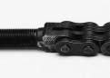
American Leaf Chain Conventional. LL series chains are developed in accordance with the ISO 606 global leaf chain regular.
A chain with an even amount of pitches always has a one male and 1 female finish. It is actually more common to have the chain possess an odd amount of pitches during which case the both ends are going to be either male (most common) or female (much less com-mon). When ordering lengths with an odd quantity of pitches male ends are provided except if otherwise mentioned. Clevis pins, ordinarily with cotters at just about every finish, are applied to connect male chain ends to female clevis blocks. Chains with female ends are sometimes (but not usually) linked on the clevis block with a cottered style connecting website link. The connecting website link will be the female finish element in this case.
Leaf Chain Assortment
Utilize the following formula to verify the variety of leaf chain:
Minimal Ultimate Strength > T x DF x SF
T: Calculated Greatest Chain Stress
DF: Duty Issue
SF: Support Aspect
Note that the highest allowable chain speed for leaf chains is 100ft per minute.