Description
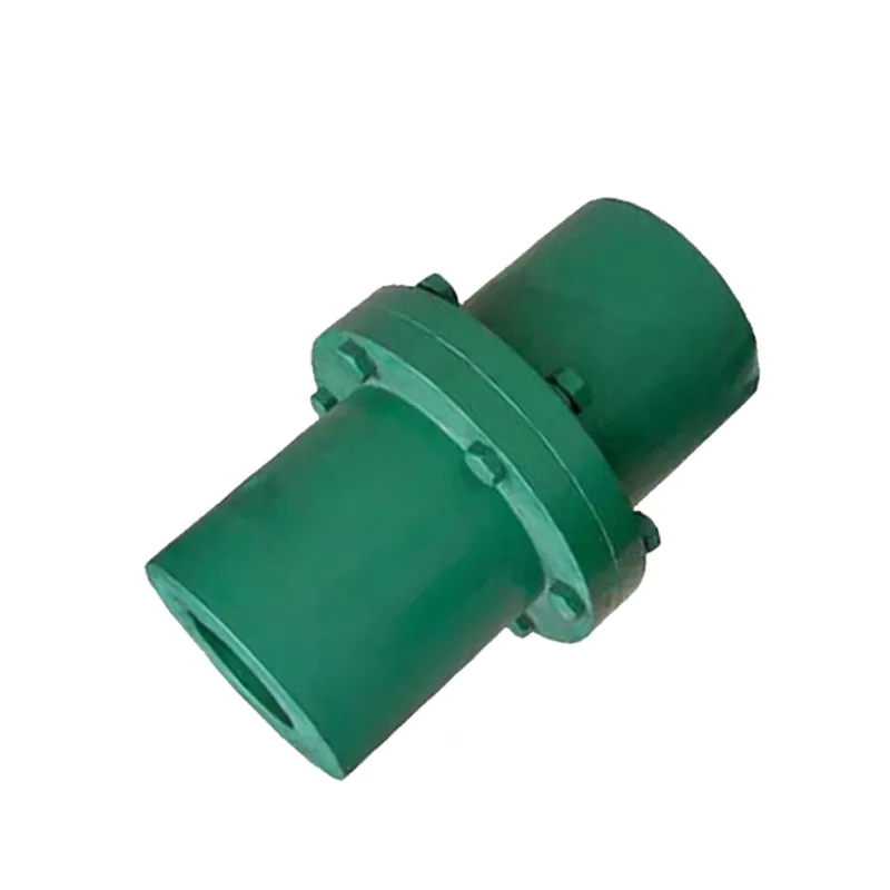
GY3/GYS3/GYH3 Flanged Coupling – 20–28mm Bore Rigid Flange Coupling to GB/T 5843-2003
The GY3/GYS3/GYH3 type flanged coupling is the most widely used rigid coupling for cylindrical shaft connections in industrial machinery — conforming to Chinese national standard GB/T 5843-2003. Three structural subtypes are available within each model number: GY type, which uses a hinge bolt hole system allowing assembly and disassembly without moving the coupling along the axial direction; GYS type, which adds a precision alignment boss (凸楔) at the flange mating face to ensure accurate shaft concentricity on reassembly without realignment measurement; and GYH type, which uses a ring (sleeve) design that assembles and disassembles by axial movement. All three subtypes share the same outer diameter (100 mm), bore range (20–28 mm), nominal torque (112 N·m), and maximum speed (9500 rpm). Entering the medium-small bore class, GY3/GYS3/GYH3 serves 20–28 mm shafts at 9500 rpm. The 112 N·m torque rating covers the 1–4 kW motor output range. GYH3 type provides the ring assembly method option for installations where axial coupling access is limited.
The coupling transmits torque through a bolted flange joint — each hub mounts on one shaft via keyway and key, and the two hub flanges are bolted together with reamed-hole precision bolts. This provides a rigid, zero-backlash connection with no flexible elements. The GY-type hinge bolt design allows the coupling to be disconnected by removing the flange bolts without requiring either shaft to move axially — a significant maintenance advantage over sleeve couplings. The GYS-type alignment boss further improves maintenance efficiency by ensuring the two hub halves re-centre precisely on reconnection, eliminating the need for dial indicator verification after each coupling reconnection in planned maintenance schedules.
Shaft hole dimensions and keyway forms comply with GB3852-1997. Both Y-type and J-type bores are available; tapered bores are also available. The complete GY/GYS/GYH coupling series is listed on our product catalog page.
Technical Specifications
| Parameter | Value |
|---|---|
| Model Numbers | GY3, GYS3, GYH3 |
| Standard | GB/T 5843-2003 |
| Bore Range (d1, d2) | 20–28 mm |
| Outer Diameter (D) | 100 mm |
| Flange Boss Width (b) | 30 mm |
| Ring Width (b1, GYH) | 46 mm |
| Face Gap (S) | 6 mm |
| Nominal Torque (Tn) | 112 N·m |
| Maximum Speed [n] | 9500 rpm |
| Rotational Inertia | 0.0025 kg·m² |
| Mass (approx.) | 2.38 kg |
| Material | Cast Iron (HT200) standard; cast steel available |
| Bore Type | Y-type, J-type, or tapered bore |
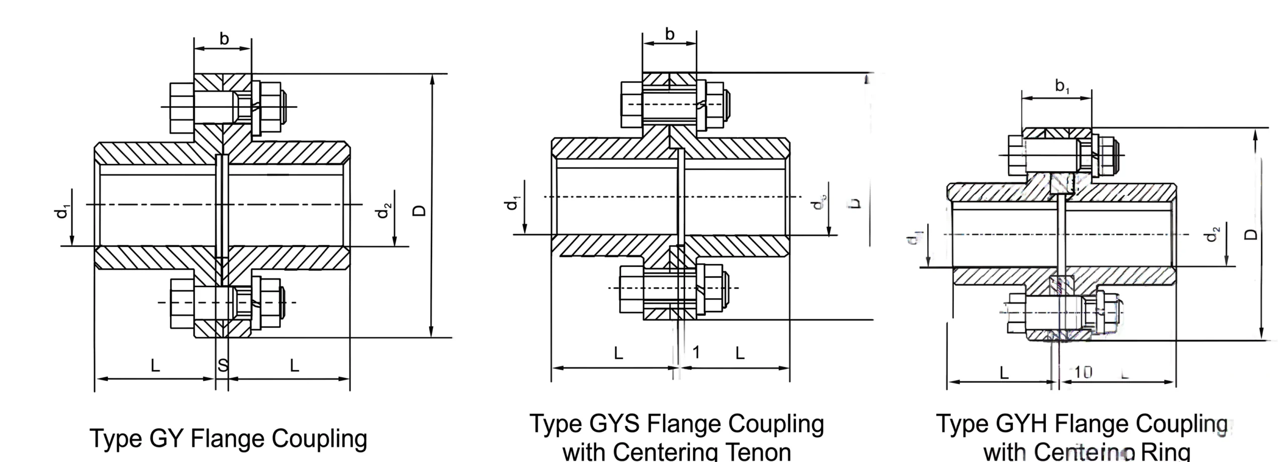
GY, GYS and GYH Subtype Dimension Reference
Three Subtype Comparison
GY Type – Hinge Bolt
The standard GY type uses a hinge bolt hole system. Assembly and disassembly are performed by removing the flange bolts — no axial shaft movement required. This is the simplest GY subtype and is specified when maintenance reconnection frequency is low or when realignment is acceptable.
GYS Type – Alignment Boss
GYS type adds a precision alignment boss (凸楔) at the flange mating face. When reassembled after maintenance, the boss centres the two hub halves concentrically, eliminating realignment measurement. Specified where frequent planned maintenance disconnection is required and realignment time must be minimised.
GYH Type – Ring Design
GYH type uses a ring (sleeve) structural element and assembles by axial movement along the shaft. This method suits installations where the coupling geometry requires axial assembly access. Processing convenience is noted as a feature; disassembly also moves along the axial direction.
Zero Backlash – All Subtypes
All three GY subtypes transmit torque through rigid bolted flange joints and key-keyway shaft connections — providing absolute zero backlash. The rated 112 N·m and 9500 rpm apply equally to GY, GYS, and GYH configurations.
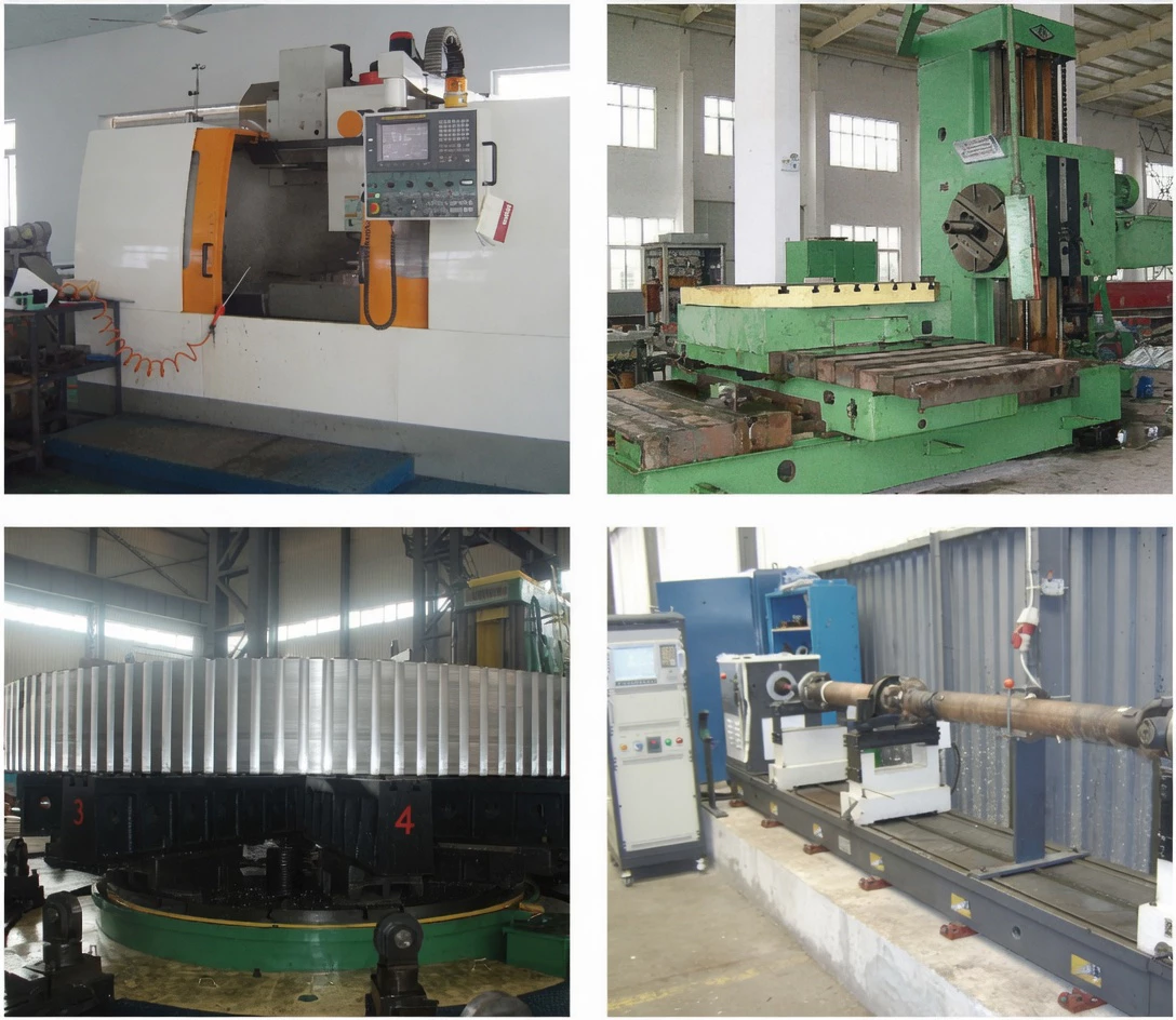
Manufacturing Quality
Typical Applications
- Large centrifugal pump motor connections — GYS type for API pump maintenance access and realignment-free reconnection
- Compressor and blower motor shaft connections — rigid flanged coupling for sustained high-torque drives
- Paper machine roll and dryer section drive connections — flanged coupling for frequent maintenance disconnection
- Mining equipment auxiliary drive connections — robust rigid flanged coupling for hostile environment drives
For volume supply and custom bore configurations, visit our contact page.
Customer Reviews and Case Studies
★★★★★
Netherlands — Industrial Fan OEM
The GY3, GYS3, and GYH3 type flanged couplings connect motor to fan shaft in our industrial duct fan product range. All three subtypes are specified depending on installation requirements — GY for simplicity, GYS where realignment-free reconnection is needed, GYH where the tapered bore suits our assembly sequence.
— Product Engineer, Rotterdam
★★★★★
India — Chemical Mixing Equipment
GY3 and GYS3 type couplings are installed on agitator drive shaft connections in our mixing equipment range. The GYS3 alignment boss speeds up our agitator maintenance reconnection procedure significantly.
— Equipment Engineer, Pune
★★★★☆
Mexico — Food Processing Plant
Used GY3 type couplings on conveyor drive connections. The rigid flanged coupling meets our food industry requirements and the flange design allows shaft section removal during equipment cleaning validation.
— Plant Engineer, Monterrey
Frequently Asked Questions
What torque safety factor should be applied when selecting a GY/GYS/GYH coupling?
Apply a torque safety factor of 1.5 to 2.5 depending on the load type: 1.5 for smooth continuous loads (pumps, fans operating at steady state); 2.0 for moderate shock or cyclic loads (compressors, textile machinery with cyclic loading); 2.5 for high shock or reversing loads. The application torque multiplied by the safety factor should not exceed the coupling’s nominal torque Tn.
Is the GY/GYS/GYH coupling suitable for applications with frequent disconnection?
Yes. The GY type hinge bolt design allows the coupling to be disconnected by removing the flange bolts without moving either shaft axially — making it suitable for applications where regular disconnection for maintenance is required. The GYS type adds the alignment boss to ensure accurate shaft concentricity on reconnection without realignment measurement.
What shaft alignment is required before installing a GY/GYS/GYH coupling?
Both shaft ends must be accurately aligned before connecting the coupling. Recommended tolerances: parallel shaft offset ≤ 0.03–0.05 mm; angular deviation ≤ 0.05 mm/m. Use a dial indicator or laser alignment tool. For GYS type, initial installation alignment is still required — the alignment boss only ensures repeatability on subsequent reconnections, not correction of initial misalignment.
How are the flange bolts specified for GY/GYS/GYH couplings?
Flange bolts are reamed-hole precision fit bolts (铰制孔螺栓). The bolt size varies by model: GY1-GY7 use 6 bolts with smaller diameters; GY8-GY12 use 10-12 bolts with larger diameters. All bolts should be tightened to the same torque using a calibrated wrench in a cross-pattern sequence.
What is the maximum speed rating basis for GY/GYS/GYH couplings?
The maximum speed limit is based on peripheral velocity of the coupling outer diameter — typically 30 m/s for cast iron. The listed maximum rpm is calculated as n_max = (30 × 60 × 1000) / (π × D) where D is the outer diameter in mm. For higher speeds, cast steel hubs with higher allowable peripheral velocity can be specified.
Source GY3/GYS3/GYH3 Flanged Couplings
Ever Power manufactures GY, GYS, and GYH type flanged couplings from GY1 to GY12 per GB/T 5843-2003, direct from our factory. Specify subtype (GY/GYS/GYH), bore sizes, bore type (Y/J/tapered), and material for a prompt technical and commercial response.