Description
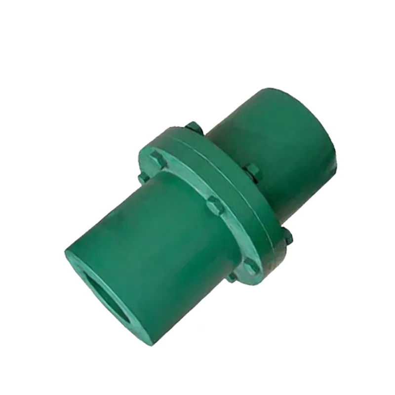
YLD4 YLD Type Flanged Coupling – 18–56mm Bore Rigid Bolted-Flange Shaft Connector to GB5843-86
The YLD4 YLD type flanged coupling is a YLD type flanged coupling with alignment tenon and spacer body designed to connect two co-axial cylindrical shaft ends rigidly through a bolted flange joint, conforming to Chinese national standard GB5843-86. With a 100 mm outer diameter, 18–56 mm bore range, and nominal torque rating of 40 N·m, the YLD4 serves shaft connections in industrial drives where a rigid, zero-backlash connection is required combined with the ability to disconnect the two shaft ends by removing the flange bolts — without moving either shaft axially. Maximum speed rating is 5700 rpm for cast iron hubs and 9500 rpm for cast steel hubs. Overall length including spacer: 308 mm (spacer length L0 = 108 mm). The spacer body provides maintenance access clearance between the two hub faces.
The YL type flanged coupling consists of two identical hub halves, each machined with a bore and keyway to receive one shaft end, and each terminating in a precision-machined circular flange. The two flanges are bolted together with 3×M8 reamed-hole precision bolts that both clamp the faces together and transmit shear torque through the bolt shank. Torque is transmitted from each shaft into its hub through the key-keyway engagement, through the hub body to the flange face, and across the bolted joint to the opposing hub and shaft. The result is a rigid, zero-backlash connection that can be separated by removing the 3 flange bolts without disturbing shaft alignment — an advantage over sleeve couplings that require axial shaft movement for installation or removal. The YLD type’s precision alignment tenon on each flange face ensures that the two hub halves re-centre automatically when the bolts are tightened after maintenance reassembly, eliminating the need for dial indicator realignment.
The YLD4 conforms to GB5843-86, which specifies dimensions for flanged couplings for cylindrical shaft connections transmitting nominal torques from 10 to 20,000 N·m. Bore and keyway dimensions conform to GB3852-1997. The complete YL and YLD flanged coupling range is listed on our product catalog page.
Technical Specifications
| Parameter | Value |
|---|---|
| Model | YLD4 |
| Type | YLD Type Flanged Coupling with Alignment Tenon |
| Standard | GB 5843-86 |
| Bore Range (d) | 18–56 mm |
| Outer Diameter (D) | 100 mm |
| Flange Diameter (D1) | 80 mm |
| Overall Length (L) | 308 mm |
| Spacer / Face Distance (L0) | 108 mm |
| Flange Bolts | 3×M8 |
| Nominal Torque (Tn) | 40 N·m |
| Max Speed – Cast Iron | 5700 rpm |
| Max Speed – Cast Steel | 9500 rpm |
| Rotational Inertia | 0.014 kg·m² |
| Mass | 4.0 kg |
Structure Drawing
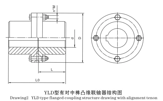
Dimension Reference
Rigid Zero-Backlash Connection
The bolted flange joint transmits torque rigidly with zero angular play. Every rotational increment on the driving shaft is replicated exactly on the driven shaft — essential for position feedback and phase-critical drive applications.
Disconnect Without Shaft Movement
Removing the flange bolts disconnects the two shaft ends without moving either shaft axially. This allows motor removal, driven equipment service, or shaft inspection without disturbing bearing housings or shaft alignment.
Cast Iron / Cast Steel Options
Hub material choice of cast iron (5700 rpm) or cast steel (9500 rpm) covers both standard industrial speed requirements and higher-speed applications. The torque rating is the same for both materials.
GB5843-86 Standard Compliance
Full conformance to national standard GB5843-86 ensures dimensional interchangeability with other GB-compliant couplings. Keyway dimensions per GB3852-1997 ensure compatibility with standard motor and driven equipment shaft keyways.
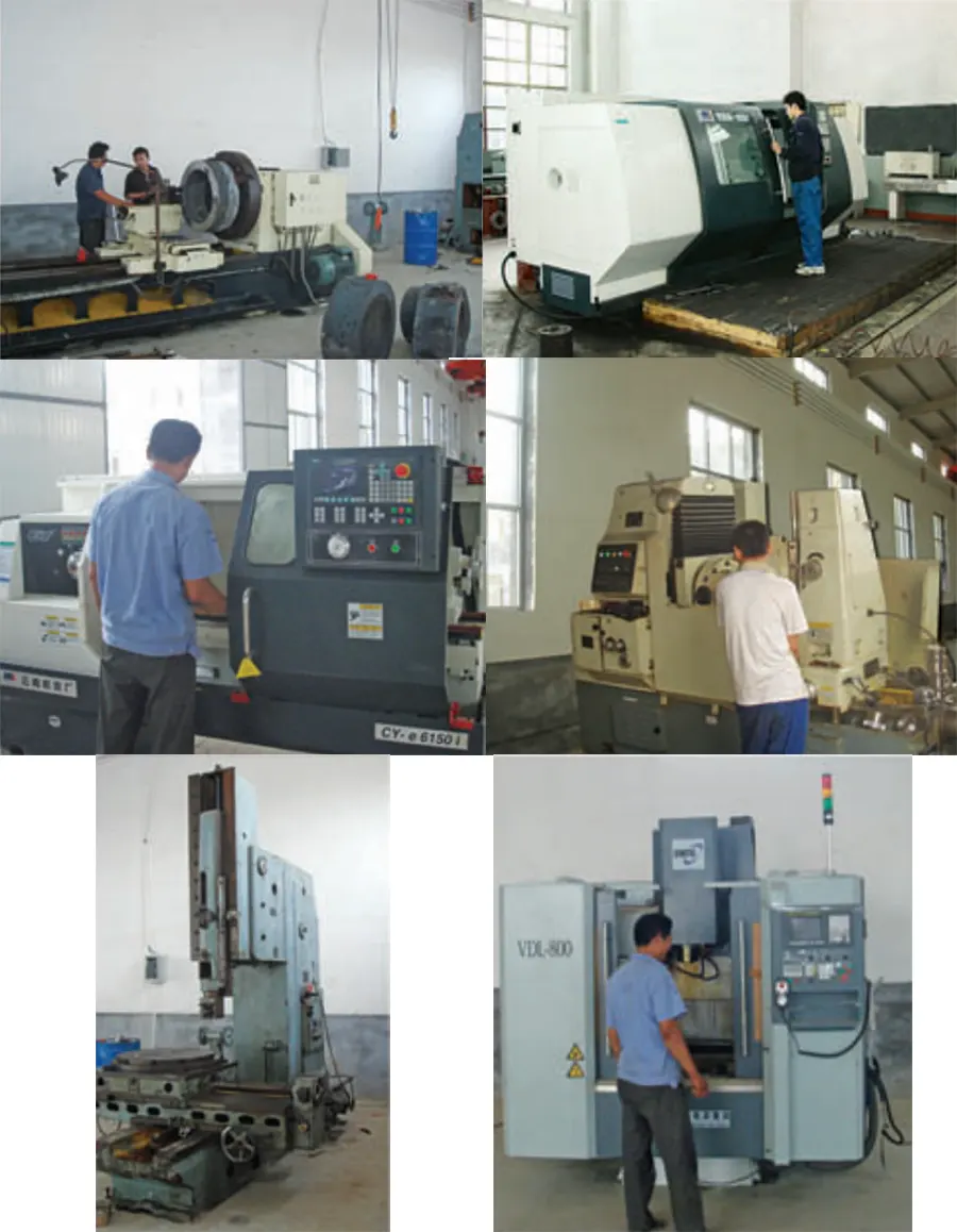
Manufacturing
Typical Applications
- Large API pump drive couplings — spacer length per API 610 seal access requirement
- Heavy industrial pump motor connections — spacer flanged coupling for large process pump seal service
- Water supply and treatment pump drives — spacer coupling for maintenance access in large pump stations
- Large industrial mixer drive connections — spacer coupling for agitator seal access in large reactor vessels
For custom bore configurations and volume supply, contact our technical team.
Customer Reviews and Case Studies
★★★★★
Germany — Industrial Pump Engineering
The YLD4 provides the access clearance needed for double mechanical seal service on our API process pump range. At 40 N·m and 308 mm spacer length, the coupling covers our mid-range API pump specifications and the alignment tenon enables our quick-seal-change maintenance procedure.
— Design Engineer, Düsseldorf
★★★★★
Norway — Offshore Platform Operations
We use YLD4 spacer couplings on our seawater injection pump drives. The spacer body allows seal inspection and replacement during production without pulling the motor — critical for our remote offshore maintenance scheduling.
— Rotating Equipment Engineer, Stavanger
★★★★☆
South Korea — Process Pump OEM
Used throughout our chemical process pump range. The YLD4 spacer length is dimensioned to our seal manufacturer’s removal clearance requirement and the alignment tenon eliminates post-reassembly alignment verification from our maintenance procedure.
— Applications Engineer, Busan
Frequently Asked Questions
What is the maximum speed difference between cast iron and cast steel versions?
The speed limit is based on peripheral velocity: 30 m/s for cast iron, 50 m/s for cast steel. For example, YL5 cast iron: 5,500 rpm; cast steel: 9,000 rpm. For applications operating above the cast iron speed limit, specify cast steel when ordering. The torque ratings are the same for both materials.
How is the YLD type spacer body connected between the two hub flanges?
The spacer tube is a machined cylindrical or flanged tube fixed between the two hub flange faces by the same bolt circle that connects the hubs. The alignment tenon on the spacer end faces locates concentrically with each hub. The spacer is a third component in addition to the two hubs — all three are bolted together to form the complete coupling assembly.
Are drawings and dimensional data available for YL/YLD couplings?
Yes. Dimensional drawings in PDF and DXF format are available on request for all YL and YLD models and bore configurations. Specify the model, bore sizes, and hub types (Y or J₁) when requesting drawings.
What is the application-level difference between YL and YLD type?
YL is specified when shaft maintenance does not require access to the coupling region and re-alignment on reconnection is acceptable. YLD is specified when: (1) shaft seals require access with the coupling in place; (2) the spacer body length matches a pump API seal access dimension; (3) the alignment tenon eliminates realignment time in high-frequency maintenance schedules.
Is the YL type coupling balanced as standard?
Standard YL and YLD couplings at smaller frame sizes rely on geometric symmetry for inherent balance. For high-speed applications approaching the maximum rated speed, dynamic balance correction can be provided. Specify the balance grade required (ISO 1940 G6.3 or G2.5) when enquiring.
Source the YLD4 YLD Flanged Coupling
Ever Power manufactures the YLD4 and the complete YL/YLD flanged coupling range to GB5843-86 direct from our factory. Specify bore sizes, hub type (Y or J₁), and material (cast iron or cast steel) for a prompt technical and commercial response.