Description
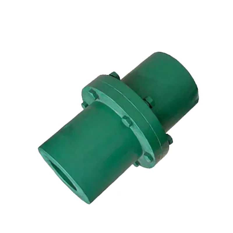
YL2 YL Type Flanged Coupling – 12–32mm Bore Rigid Bolted-Flange Shaft Connector to GB5843-86
The YL2 YL type flanged coupling is a YL type flanged coupling designed to connect two co-axial cylindrical shaft ends rigidly through a bolted flange joint, conforming to Chinese national standard GB5843-86. With a 80 mm outer diameter, 12–32 mm bore range, and nominal torque rating of 16 N·m, the YL2 serves shaft connections in industrial drives where a rigid, zero-backlash connection is required combined with the ability to disconnect the two shaft ends by removing the flange bolts — without moving either shaft axially. Maximum speed rating is 7200 rpm for cast iron hubs and 12000 rpm for cast steel hubs. Overall hub length: 80 mm, face distance L0: 88 mm.
The YL type flanged coupling consists of two identical hub halves, each machined with a bore and keyway to receive one shaft end, and each terminating in a precision-machined circular flange. The two flanges are bolted together with 4×M6 reamed-hole precision bolts that both clamp the faces together and transmit shear torque through the bolt shank. Torque is transmitted from each shaft into its hub through the key-keyway engagement, through the hub body to the flange face, and across the bolted joint to the opposing hub and shaft. The result is a rigid, zero-backlash connection that can be separated by removing the 4 flange bolts without disturbing shaft alignment — an advantage over sleeve couplings that require axial shaft movement for installation or removal.
The YL2 conforms to GB5843-86, which specifies dimensions for flanged couplings for cylindrical shaft connections transmitting nominal torques from 10 to 20,000 N·m. Bore and keyway dimensions conform to GB3852-1997. The complete YL and YLD flanged coupling range is listed on our product catalog page.
Technical Specifications
| Parameter | Value |
|---|---|
| Model | YL2 |
| Type | YL Type Flanged Coupling |
| Standard | GB 5843-86 |
| Bore Range (d) | 12–32 mm |
| Outer Diameter (D) | 80 mm |
| Flange Diameter (D1) | 64 mm |
| Overall Length (L) | 80 mm |
| Spacer / Face Distance (L0) | 88 mm |
| Flange Bolts | 4×M6 |
| Nominal Torque (Tn) | 16 N·m |
| Max Speed – Cast Iron | 7200 rpm |
| Max Speed – Cast Steel | 12000 rpm |
| Rotational Inertia | 0.0035 kg·m² |
| Mass | 1.5 kg |
Structure Drawing
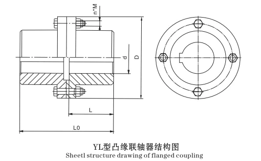
Dimension Reference
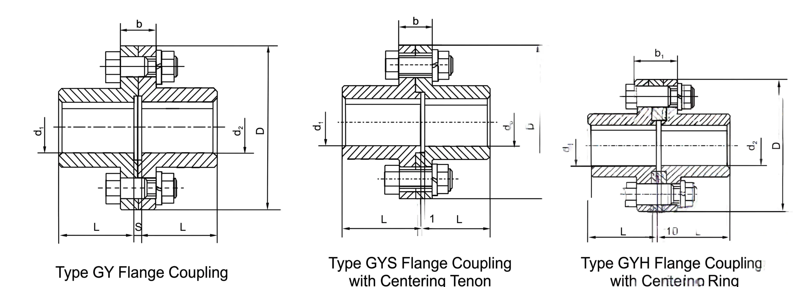
Rigid Zero-Backlash Connection
The bolted flange joint transmits torque rigidly with zero angular play. Every rotational increment on the driving shaft is replicated exactly on the driven shaft — essential for position feedback and phase-critical drive applications.
Disconnect Without Shaft Movement
Removing the flange bolts disconnects the two shaft ends without moving either shaft axially. This allows motor removal, driven equipment service, or shaft inspection without disturbing bearing housings or shaft alignment.
Cast Iron / Cast Steel Options
Hub material choice of cast iron (7200 rpm) or cast steel (12000 rpm) covers both standard industrial speed requirements and higher-speed applications. The torque rating is the same for both materials.
GB5843-86 Standard Compliance
Full conformance to national standard GB5843-86 ensures dimensional interchangeability with other GB-compliant couplings. Keyway dimensions per GB3852-1997 ensure compatibility with standard motor and driven equipment shaft keyways.
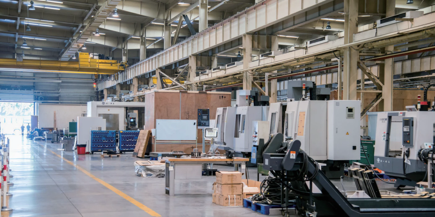
Manufacturing
Typical Applications
- Printing machine roll and shaft drive connections — zero-backlash for phase-critical print registration
- Agricultural and processing machinery drive connections — seasonal disconnection capability without shaft realignment
- Agitator and mixer drive shaft connections — rigid flanged coupling for precision speed control
- Paper machine roll drive connections — sustained torque rigid shaft coupling with maintenance access
For custom bore configurations and volume supply, contact our technical team.
Customer Reviews and Case Studies
★★★★★
United Kingdom — Printing Machine OEM
YL2 flanged couplings connect print shaft sections on our web offset printing presses. The alignment tenon on the YLD type ensures accurate shaft concentricity on reassembly after maintenance. We have used this coupling family for over five years without a shaft alignment issue on reconnection.
— Lead Mechanical Engineer, Leeds
★★★★★
France — Agricultural Machinery OEM
Installed on PTO drive shaft connections in our tractor-mounted equipment range. The YL2 handles our shaft torque reliably and the bolted flange connection can be disconnected seasonally for equipment storage without requiring shaft realignment.
— Design Engineer, Toulouse
★★★★☆
Brazil — Mining Equipment
Used on auxiliary drive shaft connections at our iron ore processing facility. The YL2 flanged coupling provides the rigid zero-backlash connection required for our position feedback drive and the flange bolts allow disconnection during planned maintenance.
— Equipment Engineer, Belo Horizonte
Frequently Asked Questions
What material are YL/YLD flanged coupling hubs made from?
Hubs are available in cast iron (HT200) and cast steel (ZG45). Cast iron is the standard material; cast steel provides higher speed ratings and is used when the maximum speed for the cast iron version is exceeded. The speed rating difference is significant: cast iron at 30 m/s peripheral velocity limit; cast steel at 50 m/s.
How many flange bolts does the YL flanged coupling use?
The number of flange bolts varies by model size: YL1-YL2 use 3 bolts (M6); YL3-YL6 use 3-4 bolts (M8); YL7-YL8 use 4 bolts (M10). Reamed hole bolts are used for precision bolt fit — tightened to a specified torque using a calibrated wrench.
Can the YL type coupling be disassembled without axial shaft movement?
Yes. This is a key advantage of the flanged coupling over the sleeve coupling. The flange bolts are removed and the two hub halves separate at the flange joint face without requiring either shaft to move axially. This allows motor or driven equipment removal for service without disturbing shaft alignment.
What is the Lo dimension on the YL coupling drawing?
L0 is the distance between the outer faces of the two hub flanges — essentially the gap or spacer distance at the coupling centre. For YL type, L0 is short (minimal gap). For YLD type, L0 is the spacer tube length, providing a larger access gap between the two hub faces for maintenance access to seals, bearings, or shaft connections in the coupling region.
Is the YL/YLD flanged coupling suitable for reversing drive applications?
Yes. The rigid bolted flange connection transmits torque equally in both rotational directions. For high-cycle reversing applications, verify that the flange bolt preload is sufficient to prevent fretting at the bolt holes and ensure the keyway bearing stress is within limits for the reversal torque.
Source the YL2 YL Flanged Coupling
Ever Power manufactures the YL2 and the complete YL/YLD flanged coupling range to GB5843-86 direct from our factory. Specify bore sizes, hub type (Y or J₁), and material (cast iron or cast steel) for a prompt technical and commercial response.