Product Description
FAQ
Q:Is your company a trading company or a manufacturer?
A: We have our own factory.
Q:How long does the lead time take?
A: If the goods are in stock, it is generally 1-2 days; if the goods are not in stock, it is 5-10 days, depending on the quantity.
Q: Can I order shaft bore couplings that are not listed in the catalog?)(Additional machining service for coupling shaft hole
A:Of course.In addition, the recommended dimensional tolerance for the applicable shaft diameter is H7.
Q: How to handle when the received parts are of poor quality?
A:If there is any non-conformity of the product, please contact us immediately, we will check the problem in the first time, and rework or repair.
Q: Why choose XingHe Precision Transmission ?
A:As a professional manufacturer of coupling , we possess a skillful team of workers and designers To provide our customers with first-class services.

Specific Safety Precautions When Working with Shaft Couplings
Working with shaft couplings involves handling rotating machinery and mechanical components. To ensure the safety of personnel and prevent accidents, specific safety precautions should be followed during installation, maintenance, and operation:
1. Lockout-Tagout (LOTO):
Prior to any work on machinery involving couplings, implement a lockout-tagout procedure to isolate the equipment from its power source. This ensures that the machinery cannot be accidentally energized during maintenance or repair, protecting workers from potential hazards.
2. Personal Protective Equipment (PPE):
Always wear appropriate personal protective equipment (PPE), including safety goggles, gloves, and appropriate clothing, when working with shaft couplings. PPE helps protect against potential hazards such as flying debris, sharp edges, or contact with moving parts.
3. Proper Training and Supervision:
Only trained and authorized personnel should work with shaft couplings. Ensure that workers have the necessary knowledge and experience to handle the equipment safely. Adequate supervision may be required, especially for less-experienced personnel.
4. Inspection and Maintenance:
Regularly inspect shaft couplings and associated components for signs of wear, damage, or misalignment. Address any issues promptly to prevent equipment failure and potential accidents.
5. Follow Manufacturer’s Guidelines:
Adhere to the manufacturer’s instructions and guidelines for installation, operation, and maintenance of the specific coupling model. Improper use or deviation from recommended procedures may compromise safety and void warranties.
6. Avoid Overloading:
Do not exceed the torque and speed limits specified by the coupling manufacturer. Overloading a coupling can lead to premature failure and pose safety risks to operators and nearby equipment.
7. Shaft Guards and Enclosures:
Install appropriate guards and enclosures to prevent accidental contact with rotating shafts and couplings. These safety measures help reduce the risk of entanglement and injuries.
8. Zero Energy State:
Ensure that all stored energy in the equipment, such as compressed air or hydraulic pressure, is released and the equipment is in a zero energy state before starting work.
9. Avoid Loose Clothing and Jewelry:
Remove or secure loose clothing, jewelry, and other items that could get caught in moving parts.
10. Maintain a Clean Work Area:
Keep the work area clean and free from clutter to avoid tripping hazards and facilitate safe movement around the machinery.
By following these safety precautions, personnel can minimize the risks associated with working with shaft couplings and create a safer working environment for everyone involved.
“`
Comparing Shaft Couplings with Other Types of Couplings in Performance
Shaft couplings are essential components in mechanical power transmission systems, and their performance characteristics vary depending on the coupling type. Let’s compare shaft couplings with other common types of couplings:
1. Shaft Couplings:
Shaft couplings come in various designs, including flexible and rigid couplings. They are widely used in a broad range of applications due to their ability to transmit torque and accommodate misalignments between rotating shafts. Flexible shaft couplings, with elastomeric or metallic elements, offer good misalignment compensation and damping characteristics. Rigid couplings, on the other hand, provide precise torque transmission and are ideal for applications where shafts are well-aligned.
2. Gear Couplings:
Gear couplings are robust and designed for heavy-duty applications. They consist of two external gear hubs with internal gear teeth that mesh together. Gear couplings can handle high torque, high-speed, and angular misalignment. They are often used in demanding industries such as steel, mining, and paper manufacturing.
3. Grid Couplings:
Grid couplings feature a flexible grid element between the two halves of the coupling. They provide excellent shock absorption and misalignment compensation. Grid couplings are commonly used in pumps, compressors, and other industrial machinery.
4. Disc Couplings:
Disc couplings utilize flexible metallic discs to transmit torque and compensate for misalignment. They offer high torsional stiffness, making them suitable for applications requiring precise motion control, such as robotics and CNC machines.
5. Jaw Couplings:
Jaw couplings consist of two hubs with elastomeric spider inserts. They are easy to install, have good misalignment capabilities, and offer electrical isolation between shafts. Jaw couplings are widely used in light to medium-duty applications.
6. Oldham Couplings:
Oldham couplings have three discs—two outer discs with slots and a central disc with a tongue that fits into the slots. They provide excellent angular misalignment compensation while maintaining constant velocity between shafts. Oldham couplings are commonly used in printing machines and conveyors.
7. Beam Couplings:
Beam couplings are made from a single piece of flexible material with spiral cuts. They offer good misalignment compensation and torsional flexibility, making them suitable for precision equipment like encoders and servo motors.
The choice of coupling depends on the specific requirements of the application, including torque, speed, misalignment compensation, environmental conditions, and space limitations. Each coupling type has its strengths and limitations, and selecting the right coupling is crucial to ensure optimal performance and reliability in the mechanical system.
“`
How Does a Flexible Shaft Coupling Differ from a Rigid Shaft Coupling?
Flexible shaft couplings and rigid shaft couplings are two distinct types of couplings, each designed to serve different purposes in mechanical power transmission. Here are the key differences between the two:
1. Flexibility:
The most significant difference between flexible and rigid shaft couplings is their flexibility. Flexible couplings are designed with elements that can deform or flex to accommodate misalignments between the shafts. This flexibility allows for angular, parallel, and axial misalignments, making them suitable for applications where shafts are not perfectly aligned. In contrast, rigid couplings do not have this flexibility and require precise alignment between the shafts.
2. Misalignment Compensation:
Flexible couplings excel in compensating for misalignments, making them ideal for applications with dynamic conditions or those prone to misalignment due to thermal expansion or vibrations. Rigid couplings, on the other hand, are used in applications where perfect alignment is critical to prevent vibration, wear, and premature failure.
3. Damping Properties:
Flexible couplings, particularly those with elastomeric or flexible elements, offer damping properties, meaning they can absorb and reduce shocks and vibrations. This damping capability helps protect the connected equipment from damage and enhances system reliability. Rigid couplings lack this damping ability and can transmit shocks and vibrations directly between shafts.
4. Torque Transmission:
Both flexible and rigid couplings are capable of transmitting torque from the driving shaft to the driven shaft. However, the torque transmission of flexible couplings can be limited compared to rigid couplings, especially in high-torque applications.
5. Types of Applications:
Flexible couplings find applications in a wide range of industries, especially in situations where misalignment compensation, vibration damping, and shock absorption are essential. They are commonly used in conveyors, pumps, compressors, printing presses, and automation systems. Rigid couplings are used in precision machinery and applications that demand perfect alignment, such as high-speed spindles and certain types of precision equipment.
6. Installation:
Flexible couplings are relatively easier to install due to their ability to accommodate misalignment. On the other hand, rigid couplings require careful alignment during installation to ensure proper functioning and prevent premature wear.
The choice between a flexible and a rigid shaft coupling depends on the specific requirements of the application. If misalignment compensation, damping, and flexibility are critical, a flexible coupling is the preferred choice. If precision alignment and direct torque transmission are essential, a rigid coupling is more suitable.
“`

editor by CX 2023-12-04
China Hot selling CHINAMFG Customized High Torque Rigid Flexible Shaft Gear Coupling Drum Shape Curved Tooth
Product Description
Densen customized High Torque Rigid Flexible Shaft Gear Coupling Drum Shape Curved Tooth Gear Coupling
| Product Name | Densen customized High Torque Rigid Flexible Shaft Gear Coupling Drum Shape Curved Tooth Gear Coupling |
| DN mm | 16-1040mm |
| Rated Torque | 0.4~4500 kN·m |
| Allowalbe Speed | 4000~460RPM |
| Material | 45# Steel or 42CrMo |
| Application | Widely used in metallurgy, mining, engineering and other fields. |
Products show
Why Choose Us
1. One stop service:
We have 5 own factories and 50+ sub-contractors located in different areas of China to offer you one-stop manufacturing and purchasing services to help you save time and reduce procurement cost.
2. Your eyes in China:
Our commitment to quality permeates from quoting, scheduling, production, inspection to deliver into your warehouse, our QC team will remark the errors if has on QC documents for your checking before delivery as your 3rd party.
3. Your R&Dconsultant:
With professional engineers team and 29 years manufacture experience ,we would help you work out problems during new parts’ development, optimize design and recommend the most cost-effective solution.
4. Your Emergency Solver:
With continued grown factories team and our QC teams located in different areas, if customers need to expedite the delivery, we would be able to adopt another factory to produce together immediately.
5. Quality Guaranty:
No matter how long time the products delivered, we are responsible for the quality. In case the products be rejected, we would replace them or return fund according to your demand without hesitation
FAQQ1. Are you a manufacturer or a trader?
Manufacture, we have 5 own foundries, 4 in ZheJiang Province, 1 in ZHangZhoug Province
Q2. Do you have MOQ request?
1 pcs per order is ok with us , unless material is seldom used.
Q3. If I only have a sample,without drawings, can you quote then manufacture for me?
Just send us the sample, we would have the sample simulated and measured by professional equipment then issue formal drawings for
you , at the same time, we could help you optimize the design according to your demand and related processes’ feasibility.

How Does a Rigid Coupling Protect Connected Equipment from Shock Loads and Vibrations?
Rigid couplings play a crucial role in protecting connected equipment from shock loads and vibrations by providing a direct and rigid connection between the shafts. The design and properties of rigid couplings contribute to their ability to mitigate the impact of shock loads and vibrations in the following ways:
– High Stiffness: Rigid couplings are constructed from materials with high stiffness, such as steel or aluminum. This high stiffness allows them to resist deformation and bending under load, ensuring that the coupling remains stable and maintains its shape. As a result, the shock loads and vibrations are not amplified or transferred to the connected equipment.
– Immediate Torque Transmission: Rigid couplings provide immediate torque transmission between the shafts without any backlash or play. When the connected machinery experiences a sudden shock load, the rigid coupling effectively transfers the torque to the other side of the coupling without delay. This rapid and precise torque transfer prevents the shock load from causing misalignment or damaging the equipment.
– Elimination of Damping: Unlike flexible couplings, which can dampen vibrations to some extent, rigid couplings do not have any damping properties. While damping can be beneficial in certain applications, it can also allow vibrations to persist, potentially affecting the performance and reliability of the connected equipment. Rigid couplings do not introduce any additional damping, ensuring that the vibrations are not prolonged.
– Stable Connection: Rigid couplings create a stable and unyielding connection between the shafts, limiting any relative movement. This stability prevents the propagation of vibrations from one shaft to another, reducing the potential for resonance and vibration amplification.
– Minimal Maintenance: Rigid couplings require minimal maintenance due to their simple and durable design. Unlike flexible couplings that may have wear-prone elements, rigid couplings do not have parts that need regular replacement. This reliability and low maintenance contribute to their ability to provide continuous protection against shock loads and vibrations.
In applications where shock loads and vibrations are prevalent, using a rigid coupling can help protect critical machinery and components from damage and premature failure. By providing a rigid and immediate torque transmission, rigid couplings effectively isolate the connected equipment from the harmful effects of shock loads and vibrations, ensuring smooth operation and enhanced reliability.
Can Rigid Couplings Be Used in Applications with Varying Operating Temperatures?
Rigid couplings are versatile mechanical components that can be used in a wide range of applications, including those with varying operating temperatures. However, the selection of the appropriate material for the rigid coupling is crucial to ensure its reliable performance under different temperature conditions.
Material Selection: The choice of material for the rigid coupling depends on the specific operating temperature range of the application. Common materials used in manufacturing rigid couplings include steel, stainless steel, and aluminum, among others. Each material has its own temperature limitations:
– Steel: Rigid couplings made from steel are suitable for applications with moderate to high temperatures. Steel couplings can handle temperatures ranging from -40°C to around 300°C, depending on the specific grade of steel used.
– Stainless Steel: Stainless steel rigid couplings offer higher corrosion resistance and can be used in applications with more demanding temperature environments. They can withstand temperatures from -80°C to approximately 400°C.
– Aluminum: Aluminum rigid couplings are commonly used in applications with lower temperature requirements, typically ranging from -50°C to around 120°C.
Thermal Expansion: When selecting a rigid coupling for an application with varying temperatures, it is essential to consider thermal expansion. Different materials have different coefficients of thermal expansion, meaning they expand and contract at different rates as the temperature changes. If the operating temperature fluctuates significantly, the thermal expansion of the rigid coupling and the connected components must be carefully accounted for to avoid issues with misalignment or binding.
Extreme Temperature Environments: For applications with extremely high or low temperatures beyond the capabilities of traditional materials, specialized high-temperature alloys or composites may be required. These materials can withstand more extreme temperature conditions but may come with higher costs.
Lubrication: The choice of lubrication can also play a role in the suitability of rigid couplings for varying temperature applications. In high-temperature environments, consideration should be given to using high-temperature lubricants that can maintain their effectiveness and viscosity at elevated temperatures.
In conclusion, rigid couplings can indeed be used in applications with varying operating temperatures, but careful material selection, consideration of thermal expansion, and appropriate lubrication are essential to ensure reliable and efficient performance under changing temperature conditions.

Advantages of Using Rigid Couplings in Mechanical Systems:
Rigid couplings offer several advantages when used in mechanical systems. These advantages make them a preferred choice in certain applications where precise alignment and high torque transmission are essential. Here are the key advantages of using rigid couplings:
- 1. High Torque Transmission: Rigid couplings are designed to handle high torque and power transmission without any loss due to flexibility. They provide a direct and solid connection between shafts, allowing for efficient transfer of rotational motion.
- 2. Precise Alignment: Rigid couplings maintain precise alignment between connected shafts. When installed correctly, they ensure that the two shafts are perfectly aligned, which is crucial for applications where accurate positioning and synchronization are required.
- 3. Synchronous Rotation: The rigid connection provided by these couplings enables synchronous rotation of the connected shafts. This is particularly important in applications where components must move in precise coordination with each other.
- 4. Simple Design: Rigid couplings have a straightforward design with minimal moving parts. This simplicity makes them easy to install and maintain, reducing the chances of mechanical failure.
- 5. Cost-Effective: Compared to some other coupling types, rigid couplings are generally more cost-effective. Their simple design and robust construction contribute to their affordability.
- 6. High Strength and Durability: Rigid couplings are typically made from strong and durable materials such as steel, stainless steel, or aluminum. These materials can withstand heavy loads and provide long-lasting performance in demanding applications.
Rigid couplings are commonly used in various industries and applications, including high-precision machinery, robotics, automation systems, precision motion control, and machine tools. They are especially beneficial in scenarios where misalignment needs to be minimized or avoided altogether.
It’s important to note that while rigid couplings offer these advantages, they are not suitable for applications where shaft misalignment or shock absorption is required. In such cases, flexible couplings or other specialized coupling types may be more appropriate.
editor by CX 2023-12-04
China Hot selling CHINAMFG Customized High Torque Rigid Flexible Shaft Gear Coupling Drum Shape Curved Tooth
Product Description
Densen customized High Torque Rigid Flexible Shaft Gear Coupling Drum Shape Curved Tooth Gear Coupling
| Product Name | Densen customized High Torque Rigid Flexible Shaft Gear Coupling Drum Shape Curved Tooth Gear Coupling |
| DN mm | 16-1040mm |
| Rated Torque | 0.4~4500 kN·m |
| Allowalbe Speed | 4000~460RPM |
| Material | 45# Steel or 42CrMo |
| Application | Widely used in metallurgy, mining, engineering and other fields. |
Products show
Why Choose Us
1. One stop service:
We have 5 own factories and 50+ sub-contractors located in different areas of China to offer you one-stop manufacturing and purchasing services to help you save time and reduce procurement cost.
2. Your eyes in China:
Our commitment to quality permeates from quoting, scheduling, production, inspection to deliver into your warehouse, our QC team will remark the errors if has on QC documents for your checking before delivery as your 3rd party.
3. Your R&Dconsultant:
With professional engineers team and 29 years manufacture experience ,we would help you work out problems during new parts’ development, optimize design and recommend the most cost-effective solution.
4. Your Emergency Solver:
With continued grown factories team and our QC teams located in different areas, if customers need to expedite the delivery, we would be able to adopt another factory to produce together immediately.
5. Quality Guaranty:
No matter how long time the products delivered, we are responsible for the quality. In case the products be rejected, we would replace them or return fund according to your demand without hesitation
FAQQ1. Are you a manufacturer or a trader?
Manufacture, we have 5 own foundries, 4 in ZheJiang Province, 1 in ZHangZhoug Province
Q2. Do you have MOQ request?
1 pcs per order is ok with us , unless material is seldom used.
Q3. If I only have a sample,without drawings, can you quote then manufacture for me?
Just send us the sample, we would have the sample simulated and measured by professional equipment then issue formal drawings for
you , at the same time, we could help you optimize the design according to your demand and related processes’ feasibility.

How Do Rigid Couplings Compare to Other Types of Couplings in Terms of Performance?
Rigid couplings offer specific advantages and disadvantages compared to other types of couplings, and their performance depends on the requirements of the application:
1. Performance: Rigid couplings provide excellent torque transmission capabilities and are best suited for applications that demand precise and efficient power transfer. They have minimal backlash and high torsional stiffness, resulting in accurate motion control.
2. Misalignment Tolerance: Rigid couplings cannot tolerate misalignment between shafts. They require precise shaft alignment during installation, which can be time-consuming and may result in increased downtime during maintenance or repairs.
3. Vibration Damping: Rigid couplings offer no damping of vibrations, which means they may not be suitable for systems that require vibration isolation or shock absorption.
4. Maintenance: Rigid couplings are generally low maintenance since they have no moving parts or flexible elements that can wear out over time. Once properly installed, they can provide reliable performance for extended periods.
5. Space Requirements: Rigid couplings are compact and do not add much length to the shaft, making them suitable for applications with limited space.
6. Cost: Rigid couplings are usually more economical compared to some advanced and specialized coupling types. Their simpler design and lower manufacturing costs contribute to their affordability.
7. Application: Rigid couplings are commonly used in applications where shafts are precisely aligned and no misalignment compensation is necessary. They are prevalent in precision machinery, robotics, and applications that require accurate motion control.
In contrast, flexible couplings, such as elastomeric, jaw, or beam couplings, are designed to accommodate misalignment, dampen vibrations, and provide some degree of shock absorption. Their performance is ideal for systems where shafts may experience misalignment due to thermal expansion, shaft deflection, or dynamic loads.
In summary, rigid couplings excel in applications that demand precise alignment and high torque transmission, but they may not be suitable for systems that require misalignment compensation or vibration damping.
What Role Does a Rigid Coupling Play in Reducing Downtime and Maintenance Costs?
A rigid coupling can play a significant role in reducing downtime and maintenance costs in mechanical systems by providing a robust and reliable connection between two shafts. Here are the key factors that contribute to this:
1. Durability and Longevity: Rigid couplings are typically made from high-quality materials such as steel or stainless steel, which offer excellent durability and resistance to wear. As a result, they have a longer service life compared to some other types of couplings that may require frequent replacements due to wear and fatigue.
2. Elimination of Wear-Prone Components: Unlike flexible couplings that include moving parts or elements designed to accommodate misalignment, rigid couplings do not have any wear-prone components. This absence of moving parts means there are fewer components that can fail, reducing the need for regular maintenance and replacement.
3. Minimization of Misalignment-Related Issues: Rigid couplings require precise shaft alignment during installation. When installed correctly, they help minimize misalignment-related issues such as vibration, noise, and premature bearing failure. Proper alignment also reduces the risk of unexpected breakdowns and maintenance requirements.
4. Increased System Efficiency: The rigid connection provided by a rigid coupling ensures efficient power transmission between the two shafts. There is minimal power loss due to flexing or bending, leading to better overall system efficiency. This efficiency can result in reduced energy consumption and operating costs.
5. Low Maintenance Requirements: Rigid couplings generally require minimal maintenance compared to some other coupling types. Once properly installed and aligned, they can operate for extended periods without needing frequent inspection or adjustment.
6. Reduced Downtime: The robust and reliable nature of rigid couplings means that they are less likely to fail unexpectedly. This increased reliability helps reduce unscheduled downtime, allowing the mechanical system to operate smoothly and consistently.
7. Cost-Effective Solution: While rigid couplings may have a higher upfront cost than some other coupling types, their long-term durability and low maintenance requirements make them a cost-effective solution over the life cycle of the equipment.
In conclusion, a rigid coupling’s ability to provide a durable and dependable connection, along with its low maintenance requirements and efficient power transmission, contributes significantly to reducing downtime and maintenance costs in mechanical systems.

Types of Rigid Coupling Designs:
There are several types of rigid coupling designs available, each designed to meet specific application requirements. Here are some common types of rigid couplings:
- 1. Sleeve Couplings: Sleeve couplings are the simplest type of rigid couplings. They consist of a cylindrical sleeve with a bore in the center that fits over the shaft ends. The coupling is secured in place using setscrews or keyways. Sleeve couplings provide a solid and rigid connection between shafts and are easy to install and remove.
- 2. Clamp or Split Couplings: Clamp couplings, also known as split couplings, are designed with two halves that fit around the shafts and are fastened together with bolts or screws. The split design allows for easy installation and removal without the need to disassemble other components in the system. These couplings are ideal for applications where the shafts cannot be easily moved.
- 3. Flanged Couplings: Flanged couplings have flanges on each end that are bolted together to form a rigid connection. The flanges add stability and strength to the coupling, making them suitable for heavy-duty applications. They are commonly used in industrial machinery and equipment.
- 4. Tapered Couplings: Tapered couplings have a tapered inner diameter that matches the taper of the shaft ends. When the coupling is tightened, it creates a frictional fit between the coupling and the shafts, providing a rigid connection. These couplings are often used in applications where high torque transmission is required.
- 5. Marine or Clampshell Couplings: Marine couplings, also known as clampshell couplings, consist of two halves that encase the shaft ends and are bolted together. These couplings are commonly used in marine applications, such as propeller shafts in boats and ships.
- 6. Diaphragm Couplings: Diaphragm couplings are a type of rigid coupling that provides some flexibility to accommodate misalignment while maintaining a nearly torsionally rigid connection. They consist of thin metal diaphragms that transmit torque while compensating for minor shaft misalignments.
The choice of rigid coupling design depends on factors such as shaft size, torque requirements, ease of installation, and the level of misalignment that needs to be accommodated. It is essential to select the appropriate coupling design based on the specific needs of the application to ensure optimal performance and reliability.
editor by CX 2023-11-30
China Good quality Flexible Shaft Coupling for 3D Printer
Product Description
flexible shaft coupling for 3D printer
Quick Details
Structure: Jaw / Spider
Flexible or Rigid: Flexible
Standard or Nonstandard: Standard
Material: Aluminium
Brand Name: YD
Place of Origin: ZheJiang , China (Mainland)
Model Number: all
Certificate: ISO9001:2008
Bore forming: Made by CNC centres
Unique Feature: Exquisite Workmanship
Bore Size: Meet inch dimension
Invertory: In stock
Spider color: Red (Green and Yellow selected)
Model Number:flexible shaft coupling for 3D printer
inner Bore Dmin: 3-14mm
Inner Bore Dmax: 10-45mm
Diameter: 30mm
Length: 20-114mm
Allowable speed: 15200min-1
Invertory: In stock
Features:
1. Light weight, smal moment of inertia and high torque.
2. Getting the drive vibration buffer, and absorbing the impact generated by motor’s uneven operation
3. Effectively correcting the installation deviation of axial and radial and angular
Your kind response of below questions will help us to recommed the most suitable model to you asap.
1.Are you looking for JM type(setscrew) or JM-C type(clamp)?
2.What is coupling outer dimeter size?
3.What is coupling inner bore size and length?
4.What is coupling material(aluminium or Stainless steel )?
Dimensions:
| Model
|
Inner Diameter | Outer Diameter |
Length | Torque(N.M.) | |||
| D1 | D2 | ||||||
| Min. | Max. | Min. | Max. | ||||
| JM14 | 3 | 7 | 3 | 7 | 14 | 22 | 0.7 |
| JM16 | 3 | 7 | 3 | 7 | 16 | 22 | 0.7 |
| JM20 | 4 | 10 | 4 | 10 | 20 | 30 | 1.7 |
| JM25 | 4 | 12 | 4 | 12 | 25 | 34 | 1.7 |
| JM30 | 5 | 16 | 5 | 16 | 30 | 35 | 1.7 |
| JM40 | 6 | 24 | 6 | 24 | 40 | 66 | 4.0 |
| JM55 | 8 | 28 | 8 | 28 | 55 | 78 | 4.0 |
| JM65 | 10 | 38 | 10 | 38 | 65 | 90 | 15.0 |
| JM80 | 12 | 45 | 12 | 45 | 80 | 114 | 15.0 |
| JM95 | 14 | 55 | 14 | 55 | 95 | 126 | 15.0 |
| JM105 | 15 | 62 | 15 | 62 | 105 | 140 | 15.0 |
| JM120 | 20 | 74 | 20 | 74 | 120 | 160 | 32.0 |
| JM135 | 22 | 80 | 22 | 80 | 135 | 185 | 32.0 |
Packaging Details:
Wooden or ply cases for export standard or according to the customers
Delivery Detail:3-5 days after receiving the 30% deposit
Contact Us

Is It Possible to Replace a Shaft Coupling Without Professional Assistance?
Yes, it is possible to replace a shaft coupling without professional assistance, especially if you have some mechanical knowledge and the necessary tools. However, the ease of replacement can vary depending on the type of coupling and the complexity of the equipment. Here are some general steps to guide you through the process:
1. Safety First:
Before starting any work, ensure that the equipment is turned off and disconnected from the power source. Use appropriate personal protective equipment (PPE) to protect yourself from potential hazards.
2. Assess the Coupling Type:
Different types of couplings may have specific installation and removal methods. Identify the type of coupling you need to replace, and consult the manufacturer’s documentation or online resources for guidance.
3. Gather Tools and Materials:
Collect the necessary tools, such as wrenches, sockets, and a puller (if required), to safely remove the old coupling. Have the new coupling ready for installation, ensuring it matches the specifications of the old one.
4. Disassembly:
If your coupling is a split or clamp-style coupling, you may be able to replace it without fully disassembling the connected equipment. Otherwise, you may need to remove other components to access the coupling.
5. Remove Fasteners:
Loosen and remove any fasteners, such as set screws, that secure the old coupling to the shafts. Take care not to damage the shafts during this process.
6. Extraction:
If the old coupling is tightly fitted on the shafts, you may need to use a coupling puller or other appropriate extraction tools to safely remove it.
7. Clean and Inspect:
After removing the old coupling, clean the shaft ends and inspect them for any signs of damage or wear. Also, check for any misalignment issues that may have contributed to the old coupling’s failure.
8. Install New Coupling:
Follow the manufacturer’s instructions for installing the new coupling. Apply appropriate lubrication and ensure the coupling is correctly aligned with the shafts.
9. Fasten Securely:
Tighten the fasteners to the manufacturer’s recommended torque values to securely attach the new coupling to the shafts.
10. Test Run:
After installation, perform a test run of the equipment to ensure the new coupling operates smoothly and without issues.
While it is possible to replace a shaft coupling without professional assistance, keep in mind that some couplings and equipment may require specialized knowledge and tools for safe and proper replacement. If you are uncertain about the process or encounter any difficulties, it is advisable to seek help from a qualified professional or technician to avoid potential damage to the equipment or injury to yourself.
“`
Real-World Examples of Shaft Coupling Applications in Different Industries
Shaft couplings play a crucial role in various industries by connecting rotating shafts and transmitting torque between them. Here are some real-world examples of shaft coupling applications in different industries:
1. Manufacturing Industry:
In manufacturing plants, shaft couplings are used in various equipment such as conveyor systems, pumps, compressors, and mixers. For example, in a conveyor system, shaft couplings connect the motor shaft to the conveyor belt, allowing efficient material handling and transportation.
2. Oil and Gas Industry:
The oil and gas industry utilizes shaft couplings in applications like drilling rigs, pumps, and generators. In drilling rigs, couplings connect the motor to the drill shaft, enabling the drilling process.
3. Marine Industry:
In the marine industry, shaft couplings are found in propulsion systems, water pumps, and winches. They connect the ship’s engine to the propeller shaft, providing the necessary torque for propulsion.
4. Power Generation:
Power plants use shaft couplings in turbines, generators, and cooling systems. For instance, in a steam turbine, couplings connect the turbine to the electrical generator, allowing the conversion of steam energy into electrical power.
5. Aerospace Industry:
Aerospace applications use shaft couplings in aircraft engines, landing gear systems, and auxiliary power units. Couplings enable power transmission between different components of the aircraft systems.
6. Automotive Industry:
In vehicles, shaft couplings are present in the drivetrain, steering systems, and transmission. For example, in a car’s transmission system, couplings connect the engine to the gearbox, enabling smooth gear changes and power transmission to the wheels.
7. Mining Industry:
The mining industry relies on shaft couplings in heavy-duty machinery such as crushers, conveyor belts, and pumps. Couplings connect motors to various mining equipment, facilitating material extraction and transportation.
8. Agriculture:
Agricultural machinery like tractors and harvesters use shaft couplings to connect the engine to implements such as plows, harvesters, and irrigation pumps.
These examples demonstrate the wide-ranging applications of shaft couplings across industries. In each case, the specific coupling type is chosen based on factors such as torque requirements, misalignment compensation, environmental conditions, and load characteristics to ensure reliable and efficient operation.
“`
Best Practices for Installing a Shaft Coupling for Optimal Performance
Proper installation of a shaft coupling is crucial for ensuring optimal performance and preventing premature wear or failure. Follow these best practices to install a shaft coupling correctly:
1. Shaft Alignment:
Ensure that both the driving and driven shafts are properly aligned before installing the coupling. Misalignment can lead to increased stress on the coupling and other connected components, reducing efficiency and causing premature wear. Use alignment tools, such as dial indicators or laser alignment systems, to achieve accurate shaft alignment.
2. Cleanliness:
Before installation, clean the shaft ends and the coupling bore thoroughly. Remove any dirt, debris, or residue that could interfere with the coupling’s fit or cause misalignment.
3. Lubrication:
Apply the recommended lubricant to the coupling’s contact surfaces, such as the bore and shaft ends. Proper lubrication ensures smooth installation and reduces friction during operation.
4. Correct Fit:
Ensure that the coupling is the correct size and type for the application. Use couplings with the appropriate torque and speed ratings to match the equipment’s requirements.
5. Fastening:
Use the recommended fastening methods, such as set screws or keyways, to securely attach the coupling to the shafts. Make sure the fasteners are tightened to the manufacturer’s specifications to prevent loosening during operation.
6. Spacer or Adapter:
If required, use a spacer or adapter to properly position the coupling on the shafts and maintain the desired distance between the driving and driven components.
7. Avoid Shaft Damage:
Be careful during installation to avoid damaging the shaft ends, especially when using set screws or other fastening methods. Shaft damage can lead to stress concentrations and eventual failure.
8. Check Runout:
After installation, check the coupling’s runout using a dial indicator to ensure that it rotates smoothly and without wobbling. Excessive runout can indicate misalignment or improper fit.
9. Periodic Inspection:
Regularly inspect the coupling and its components for signs of wear, misalignment, or damage. Perform routine maintenance as recommended by the manufacturer to prevent issues from worsening over time.
10. Follow Manufacturer’s Guidelines:
Always follow the manufacturer’s installation instructions and guidelines. Different types of couplings may have specific installation requirements that need to be adhered to for optimal performance and safety.
By following these best practices, you can ensure that your shaft coupling is installed correctly, maximizing its efficiency and reliability in your mechanical power transmission system.
“`
editor by CX 2023-11-28
China Hot selling Flexible Flex Fluid Chain Jaw Flange Gear Rigid Spacer Pin HRC Mh Nm Universal Fenaflex Oldham Spline Clamp Tyre Grid Hydraulic Servo Motor Shaft Coupling
Product Description
Flexible flex Fluid Chain Jaw flange Gear Rigid Spacer PIN HRC MH NM universal Fenaflex Oldham spline clamp tyre grid hydraulic servo motor shaft Coupling
Product Description
The function of Shaft coupling:
1. Shafts for connecting separately manufactured units such as motors and generators.
2. If any axis is misaligned.
3. Provides mechanical flexibility.
4. Absorb the transmission of impact load.
5. Prevent overload
We can provide the following couplings.
| Rigid coupling | Flange coupling | Oldham coupling |
| Sleeve or muff coupling | Gear coupling | Bellow coupling |
| Split muff coupling | Flexible coupling | Fluid coupling |
| Clamp or split-muff or compression coupling | Universal coupling | Variable speed coupling |
| Bushed pin-type coupling | Diaphragm coupling | Constant speed coupling |
Company Profile
We are an industrial company specializing in the production of couplings. It has 3 branches: steel casting, forging, and heat treatment. Main products: cross shaft universal coupling, drum gear coupling, non-metallic elastic element coupling, rigid coupling, etc.
The company mainly produces the industry standard JB3241-91 swap JB5513-91 swc. JB3242-93 swz series universal coupling with spider type. It can also design and produce various non-standard universal couplings, other couplings, and mechanical products for users according to special requirements. Currently, the products are mainly sold to major steel companies at home and abroad, the metallurgical steel rolling industry, and leading engine manufacturers, with an annual production capacity of more than 7000 sets.
The company’s quality policy is “quality for survival, variety for development.” In August 2000, the national quality system certification authority audited that its quality assurance system met the requirements of GB/T19002-1994 IDT ISO9002:1994 and obtained the quality system certification certificate with the registration number 0900B5711. It is the first enterprise in the coupling production industry in HangZhou City that passed the ISO9002 quality and constitution certification.
The company pursues the business purpose of “reliable quality, the supremacy of reputation, commitment to business and customer satisfaction” and welcomes customers at home and abroad to choose our products.
At the same time, the company has established long-term cooperative relations with many enterprises and warmly welcomes friends from all walks of life to visit, investigate and negotiate business!
How to use the coupling safely
The coupling is an intermediate connecting part of each motion mechanism, which directly impacts the regular operation of each motion mechanism. Therefore, attention must be paid to:
1. The coupling is not allowed to have more than the specified axis deflection and radial displacement so as not to affect its transmission performance.
2. The bolts of the LINS coupling shall not be loose or damaged.
3. Gear coupling and cross slide coupling shall be lubricated regularly, and lubricating grease shall be added every 2-3 months to avoid severe wear of gear teeth and serious consequences.
4. The tooth width contact length of gear coupling shall not be less than 70%; Its axial displacement shall not be more significant than 5mm
5. The coupling is not allowed to have cracks. If there are cracks, it needs to be replaced (they can be knocked with a small hammer and judged according to the sound).
6. The keys of LINS coupling shall be closely matched and shall not be loosened.
7. The tooth thickness of the gear coupling is worn. When the lifting mechanism exceeds 15% of the original tooth thickness, the operating mechanism exceeds 25%, and the broken tooth is also scrapped.
8. If the elastic ring of the pin coupling and the sealing ring of the gear coupling is damaged or aged, they should be replaced in time.
Certifications
Packaging & Shipping
Industry Standards and Certifications for Rigid Shaft Couplings
Yes, there are industry standards and certifications that apply to rigid shaft couplings to ensure their quality, performance, and safety. Some of the common standards and certifications include:
- ISO 14691: This International Organization for Standardization (ISO) standard specifies the requirements and dimensions for metallic straight-toothed rigid couplings with external clamping for shaft connections.
- ANSI/AGMA 9002-C16: The American Gear Manufacturers Association (AGMA) standard covers measurement methods for evaluating the torsional stiffness of rigid couplings.
- API 671: This American Petroleum Institute (API) standard applies to special-purpose couplings used in petroleum, chemical, and gas industry services, ensuring reliable operation and safety.
- DNV GL: Rigid couplings used in marine and offshore applications may require certification from DNV GL, an international accredited registrar and classification society.
- ATEX: For couplings used in explosive atmospheres, compliance with the ATEX directive is crucial to ensure that the coupling does not become a source of ignition.
When selecting a rigid shaft coupling, it is essential to look for products that comply with these relevant industry standards and certifications. Meeting these standards guarantees that the couplings have undergone rigorous testing and adhere to recognized quality and safety guidelines.
What are the maintenance requirements for rigid shaft couplings to extend their lifespan?
Rigid shaft couplings are mechanical components used to connect two shafts and transmit torque between them. While rigid couplings are known for their durability and minimal maintenance needs, proper care and maintenance can further extend their lifespan and ensure optimal performance. Here are key maintenance considerations:
- Lubrication: Some rigid couplings, especially those with moving parts like set screws, may require periodic lubrication to reduce friction and wear. Use appropriate lubricants as recommended by the manufacturer.
- Visual Inspection: Regularly inspect the coupling for signs of wear, corrosion, or damage. Look for cracks, dents, or any other abnormalities that could affect its performance. Address any issues promptly.
- Tightening Fasteners: If the rigid coupling is secured using fasteners such as set screws or bolts, ensure they are tightened to the manufacturer’s specifications. Loose fasteners can lead to misalignment and reduced coupling effectiveness.
- Alignment Check: Periodically check the alignment of the connected shafts. Misalignment can lead to increased stress on the coupling and premature wear. Realign the shafts if necessary.
- Coupling Integrity: Make sure the coupling is securely fastened and properly seated on both shafts. Any looseness or improper fitting can lead to vibrations and wear.
- Cleanliness: Keep the coupling and surrounding area clean from dirt, debris, and contaminants. Foreign particles can lead to increased wear and reduced performance.
- Environmental Factors: Consider the operating environment. If the coupling is exposed to harsh conditions, such as extreme temperatures or corrosive substances, take appropriate measures to protect the coupling’s surfaces and materials.
- Replacement of Worn Parts: If any components of the coupling show significant wear or damage, consider replacing them as per the manufacturer’s recommendations. This can prevent further issues and maintain coupling integrity.
- Manufacturer Guidelines: Always follow the maintenance recommendations provided by the coupling manufacturer. They can provide specific guidelines based on the coupling’s design and materials.
Proper maintenance practices not only extend the lifespan of rigid shaft couplings but also contribute to the overall reliability and efficiency of the connected machinery. Regular inspections and maintenance can help identify potential issues early, preventing costly downtime and repairs.
It’s important to note that maintenance requirements can vary based on the specific design and material of the rigid coupling. Consulting the manufacturer’s documentation and seeking professional advice can help establish a suitable maintenance schedule tailored to the coupling’s characteristics and the application’s demands.

What is a Rigid Shaft Coupling and How Does It Work in Mechanical Systems?
A rigid shaft coupling is a type of coupling used to connect two shafts together in a mechanical system. As the name suggests, it is designed to provide a rigid and solid connection between the shafts, without any flexibility or misalignment compensation.
The primary function of a rigid shaft coupling is to transmit torque from one shaft to another efficiently and with minimal backlash. It achieves this by directly connecting the two shafts using a rigid mechanical interface.
Rigid shaft couplings typically consist of two halves with flanges that are bolted or clamped together around the shaft ends. The flanges are precision machined to ensure accurate alignment of the shafts. Some common types of rigid shaft couplings include:
- Sleeve Couplings: These are the simplest type of rigid couplings and consist of a cylindrical sleeve with a bore that fits over the shaft ends. The two shafts are aligned and then secured together using screws or pins.
- Clamp or Split Couplings: These couplings have two halves that are split and bolted together around the shafts. The split design allows for easy installation and removal without the need to disassemble other components of the system.
- Flanged Couplings: Flanged couplings have two flanges with precision machined faces that are bolted together, providing a robust connection.
- Tapered Bushing Couplings: These couplings use a tapered bushing to lock the coupling onto the shafts, creating a secure and concentric connection.
Rigid shaft couplings are commonly used in applications where precise alignment is critical, such as in high-speed machinery, precision instruments, and power transmission systems. Since they do not have any flexibility, they are best suited for applications where shaft misalignment is minimal or can be controlled through accurate alignment during installation.
One of the main advantages of rigid shaft couplings is their ability to provide a direct and efficient transfer of torque, making them suitable for high-torque and high-speed applications. Additionally, their simple design and solid connection make them easy to install and maintain.
However, it’s essential to ensure proper alignment during installation to prevent premature wear and stress on the shafts and other components. In cases where misalignment is expected or unavoidable, flexible couplings like beam couplings, bellows couplings, or jaw couplings are more appropriate, as they can compensate for small misalignments and provide some degree of shock absorption.
editor by CX 2023-11-09
China Custom CLB 8 Holes Double Diaphragm Series Coupler High Rigidity And Torque Coupling Clamp Flexible Coupling Series manufacturer
Guarantee: 1 12 months
Relevant Industries: Building works , Energy & Mining, Farms, Garment Shops, Property Use, Machinery Repair Shops, Manufacturing unit direct revenue AW70 AW82 85G YH700 YH850 1E6B30-73500 MITSUBOSHI rice combine harvester spare areas belt B70W800LD Production Plant, Printing Stores, Retail
Customized help: ODM, OEM
Structure: Diaphragm
Adaptable or Rigid: Adaptable
Standard or Nonstandard: Normal
Substance: Aluminium Alloy
Packaging Details: Little Parcels will use Carton Box PackingBig parcels will use wood to bolster
Model: CLB Sequence:8 Holes Double Diaphragm SeriesLength: 65~ninety six mmOutside diameter: 56~87mmBore:twelve~50 mmApplication:Servo, progressive motor, common motor connection Business Profile Advise Goods FAQ Q: Are you authentic manufacture?A: Indeed, P2SH7 helical gear reduction box reducer reducer for mining equipment we are an formal foremost manufature in air-cleaning machinery in China and we have the whole sequence goods youneed.Q: What type fo conditions of payment can be accepted?A: Usually we can work on T/T trem ,VISA ,Mastercard ,West Union .Q: What about the shipping time?A : Generally 5-15 days right after receving the deposit.Custom-made goods 10-15days soon after receving the deposit.Q: What about the Minimal Buy Quantity?A: The MOQ is 1 pcs, sample buy in little amount is acceptableQ: Can I check out your manufacturing facility prior to purchase?A: Indeed, welcome to go to our manufacturing facility. A single hour in close proximity to HangZhou Airport.Q: What is LEADTIME for manufacturing?A: Usually stock items will be shipped inside of 24 hours, Newest Design Pc200-8 Travel Gearbox Vacation Reducer custom made merchandise about 3-6 days shipping and delivery (in accordance to the quantity ofproduct)
The Benefits of Spline Couplings for Disc Brake Mounting Interfaces
Spline couplings are commonly used for securing disc brake mounting interfaces. Spline couplings are often used in high-performance vehicles, aeronautics, and many other applications. However, the mechanical benefits of splines are not immediately obvious. Listed below are the benefits of spline couplings. We’ll discuss what these advantages mean for you. Read on to discover how these couplings work.
Disc brake mounting interfaces are splined
There are two common disc brake mounting interfaces – splined and six-bolt. Splined rotors fit on splined hubs; six-bolt rotors will need an adapter to fit on six-bolt hubs. The six-bolt method is easier to maintain and may be preferred by many cyclists. If you’re thinking of installing a disc brake system, it is important to know how to choose the right splined and center lock interfaces.
Aerospace applications
The splines used for spline coupling in aircraft are highly complex. While some previous researches have addressed the design of splines, few publications have tackled the problem of misaligned spline coupling. Nevertheless, the accurate results we obtained were obtained using dedicated simulation tools, which are not commercially available. Nevertheless, such tools can provide a useful reference for our approach. It would be beneficial if designers could use simple tools for evaluating contact pressure peaks. Our analytical approach makes it possible to find answers to such questions.
The design of a spline coupling for aerospace applications must be accurate to minimize weight and prevent failure mechanisms. In addition to weight reduction, it is necessary to minimize fretting fatigue. The pressure distribution on the spline coupling teeth is a significant factor in determining its fretting fatigue. Therefore, we use analytical and experimental methods to examine the contact pressure distribution in the axial direction of spline couplings.
The teeth of a spline coupling can be categorized by the type of engagement they provide. This study investigates the position of resultant contact forces in the teeth of a spline coupling when applied to pitch diameter. Using FEM models, numerical results are generated for nominal and parallel offset misalignments. The axial tooth profile determines the behavior of the coupling component and its ability to resist wear. Angular misalignment is also a concern, causing misalignment.
In order to assess wear damage of a spline coupling, we must take into consideration the impact of fretting on the components. This wear is caused by relative motion between the teeth that engage them. The misalignment may be caused by vibrations, cyclical tooth deflection, or angular misalignment. The result of this analysis may help designers improve their spline coupling designs and develop improved performance.
CZPT polyimide, an abrasion-resistant polymer, is a popular choice for high-temperature spline couplings. This material reduces friction and wear, provides a low friction surface, and has a low wear rate. Furthermore, it offers up to 50 times the life of metal on metal spline connections. For these reasons, it is important to choose the right material for your spline coupling.
High-performance vehicles
A spline coupler is a device used to connect splined shafts. A typical spline coupler resembles a short pipe with splines on either end. There are two basic types of spline coupling: single and dual spline. One type attaches to a drive shaft, while the other attaches to the gearbox. While spline couplings are typically used in racing, they’re also used for performance problems.
The key challenge in spline couplings is to determine the optimal dimension of spline joints. This is difficult because no commercial codes allow the simulation of misaligned joints, which can destroy components. This article presents analytical approaches to estimating contact pressures in spline connections. The results are comparable with numerical approaches but require special codes to accurately model the coupling operation. This research highlights several important issues and aims to make the application of spline couplings in high-performance vehicles easier.
The stiffness of spline assemblies can be calculated using tooth-like structures. Such splines can be incorporated into the spline joint to produce global stiffness for torsional vibration analysis. Bearing reactions are calculated for a certain level of misalignment. This information can be used to design bearing dimensions and correct misalignment. There are three types of spline couplings.
Major diameter fit splines are made with tightly controlled outside diameters. This close fit provides concentricity transfer from the male to the female spline. The teeth of the male spline usually have chamfered tips and clearance with fillet radii. These splines are often manufactured from billet steel or aluminum. These materials are renowned for their strength and uniform grain created by the forging process. ANSI and DIN design manuals define classes of fit.
Disc brake mounting interfaces
A spline coupling for disc brake mounting interfaces is a type of hub-to-brake-disc mount. It is a highly durable coupling mechanism that reduces heat transfer from the disc to the axle hub. The mounting arrangement also isolates the axle hub from direct contact with the disc. It is also designed to minimize the amount of vehicle downtime and maintenance required to maintain proper alignment.
Disc brakes typically have substantial metal-to-metal contact with axle hub splines. The discs are held in place on the hub by intermediate inserts. This metal-to-metal contact also aids in the transfer of brake heat from the brake disc to the axle hub. Spline coupling for disc brake mounting interfaces comprises a mounting ring that is either a threaded or non-threaded spline.
During drag brake experiments, perforated friction blocks filled with various additive materials are introduced. The materials included include Cu-based powder metallurgy material, a composite material, and a Mn-Cu damping alloy. The filling material affects the braking interface’s wear behavior and friction-induced vibration characteristics. Different filling materials produce different types of wear debris and have different wear evolutions. They also differ in their surface morphology.
Disc brake couplings are usually made of two different types. The plain and HD versions are interchangeable. The plain version is the simplest to install, while the HD version has multiple components. The two-piece couplings are often installed at the same time, but with different mounting interfaces. You should make sure to purchase the appropriate coupling for your vehicle. These interfaces are a vital component of your vehicle and must be installed correctly for proper operation.
Disc brakes use disc-to-hub elements that help locate the forces and displace them to the rim. These elements are typically made of stainless steel, which increases the cost of manufacturing the disc brake mounting interface. Despite their benefits, however, the high braking force loads they endure are hard on the materials. Moreover, excessive heat transferred to the intermediate elements can adversely affect the fatigue life and long-term strength of the brake system.

China manufacturer Aluminum Alloy Blue Flexible Shaft Coupler Gear Motor Flexible Coupling coupling alignment tool
Warranty: 3 several years
Relevant Industries: Lodges, Garment Stores, Creating Content Shops, Manufacturing Plant, Equipment Restore Outlets, Food & Beverage Manufacturing unit, Farms, Cafe, Affluent Source Uh571-7 Swing Motor Swing Reducer Gear Property Use, Retail, Meals Store, Printing Stores, Design works , Energy & Mining, Foods & Beverage Outlets, Marketing Business
Customized help: OEM
Composition: Gear
Versatile or Rigid: Rigid
Standard or Nonstandard: Regular
Substance: Aluminium
Surface area Treatment method: chrome plating, 42BLY01A-005AG62 24V wholesale CE ROHS ISO planetary gearbox motor dc gear motor Nickel plating, polish, anodizing, and many others
Sample: available
Services: OEM ODM
Delivery time: 3-10 times
Aluminum Alloy Blue Flexible Shaft Coupler Equipment Motor Adaptable Coupling Much more Items Application of product Why Pick US? Certifications Firm Profile Overview & Contact FAQ Q1: Are you a Company or a Buying and selling Firm? A:We are a professional maker with over 11 years of experience, and have a full supply chain from elements processing to concluded goods. Q2: How is your High quality Handle? A: We have expert examining employees on each creation line approach. Right after ending the total motor, we have the entire quality equipment to take a look at the motor. This kind of as Hardness Tester, 2.5D Graphic Tester, Variable Pace Transmission Winch Appropriate Angle Spur Equipment Ratio 501 Planetary Gearbox For Servo Motor Stepping Motor Salt Spray Chamber, Existence Tester, Temperature Test Equipment, and Noise tester etc. Q3: How about Sample order? A: Sample is offered for you. please get in touch with us for specifics. As soon as we demand you sample fee,you should feel simple, it would be refund when you spot official order.This autumn: How long is the producing and delivery? A: 1. Shipping and delivery timedepends on the amount you order. generally it normally takes 7-15 operating times. 2. Standard sort merchandise can be delivered inside 3 workingdays, and other custom-made samples can be shipped inside of 7-ten doing work times. Q5: When will you reply right after received my inquiries? A: Ourcustomer support is online 24 hrs, looking forward to your inquiry.
Types of Screw Shafts
Screw shafts come in various types and sizes. These types include fully threaded, Lead, and Acme screws. Let’s explore these types in more detail. What type of screw shaft do you need? Which one is the best choice for your project? Here are some tips to choose the right screw:
Machined screw shaft
The screw shaft is a basic piece of machinery, but it can be further customized depending on the needs of the customer. Its features include high-precision threads and ridges. Machined screw shafts are generally manufactured using high-precision CNC machines or lathes. The types of screw shafts available vary in shape, size, and material. Different materials are suitable for different applications. This article will provide you with some examples of different types of screw shafts.
Ball screws are used for a variety of applications, including mounting machines, liquid crystal devices, measuring devices, and food and medical equipment. Various shapes are available, including miniature ball screws and nut brackets. They are also available without keyway. These components form a high-accuracy feed mechanism. Machined screw shafts are also available with various types of threaded ends for ease of assembly. The screw shaft is an integral part of linear motion systems.
When you need a machined screw shaft, you need to know the size of the threads. For smaller machine screws, you will need a mating part. For smaller screw sizes, the numbers will be denominated as industry Numeric Sizes. These denominations are not metric, but rather in mm, and they may not have a threads-per-inch designation. Similarly, larger machine screws will usually have threads that have a higher pitch than those with a lower pitch.
Another important feature of machine screws is that they have a thread on the entire shaft, unlike their normal counterparts. These machine screws have finer threads and are intended to be screwed into existing tapped holes using a nut. This means that these screws are generally stronger than other fasteners. They are usually used to hold together electronic components, industrial equipment, and engines. In addition to this, machine screws are usually made of a variety of materials.
Acme screw
An Acme screw is the most common type of threaded shaft available. It is available in a variety of materials including stainless steel and carbon steel. In many applications, it is used for large plates in crushing processes. ACME screws are self-locking and are ideal for applications requiring high clamping force and low friction. They also feature a variety of standard thread forms, including knurling and rolled worms.
Acme screws are available in a wide range of sizes, from 1/8″ to 6″. The diameter is measured from the outside of the screw to the bottom of the thread. The pitch is equal to the lead in a single start screw. The lead is equal to the pitch plus the number of starts. A screw of either type has a standard pitch and a lead. Acme screws are manufactured to be accurate and durable. They are also widely available in a wide range of materials and can be customized to fit your needs.
Another type of Acme screw is the ball screw. These have no back drive and are widely used in many applications. Aside from being lightweight, they are also able to move at faster speeds. A ball screw is similar to an Acme screw, but has a different shape. A ball screw is usually longer than an Acme screw. The ball screw is used for applications that require high linear speeds. An Acme screw is a common choice for many industries.
There are many factors that affect the speed and resolution of linear motion systems. For example, the nut position and the distance the screw travels can all affect the resolution. The total length of travel, the speed, and the duty cycle are all important. The lead size will affect the maximum linear speed and force output. If the screw is long, the greater the lead size, the higher the resolution. If the lead length is short, this may not be the most efficient option.
Lead screw
A lead screw is a threaded mechanical device. A lead screw consists of a cylindrical shaft, which includes a shallow thread portion and a tightly wound spring wire. This spring wire forms smooth, hard-spaced thread convolutions and provides wear-resistant engagement with the nut member. The wire’s leading and trailing ends are anchored to the shaft by means appropriate to the shaft’s composition. The screw is preferably made of stainless steel.
When selecting a lead screw, one should first determine its critical speed. The critical speed is the maximum rotations per minute based on the natural frequency of the screw. Excessive backlash will damage the lead screw. The maximum number of revolutions per minute depends on the screw’s minor diameter, length, assembly alignment, and end fixity. Ideally, the critical speed is 80% of its evaluated critical speed. A critical speed is not exceeded because excessive backlash would damage the lead screw and may be detrimental to the screw’s performance.
The PV curve defines the safe operating limits of a lead screw. This relationship describes the inverse relationship between contact surface pressure and sliding velocity. As the PV value increases, a lower rotation speed is required for heavier axial loads. Moreover, PV is affected by material and lubrication conditions. Besides, end fixity, which refers to the way the lead screw is supported, also affects its critical speed. Fixed-fixed and free end fixity are both possible.
Lead screws are widely used in industries and everyday appliances. In fact, they are used in robotics, lifting equipment, and industrial machinery. High-precision lead screws are widely used in the fields of engraving, fluid handling, data storage, and rapid prototyping. Moreover, they are also used in 3D printing and rapid prototyping. Lastly, lead screws are used in a wide range of applications, from measuring to assembly.
Fully threaded screw
A fully threaded screw shaft can be found in many applications. Threading is an important feature of screw systems and components. Screws with threaded shafts are often used to fix pieces of machinery together. Having fully threaded screw shafts ensures that screws can be installed without removing the nut or shaft. There are two major types of screw threads: coarse and fine. When it comes to coarse threads, UTS is the most common type, followed by BSP.
In the 1840s, a British engineer named Joseph Whitworth created a design that was widely used for screw threads. This design later became the British Standard Whitworth. This standard was used for screw threads in the United States during the 1840s and 1860s. But as screw threads evolved and international standards were established, this system remained largely unaltered. A new design proposed in 1864 by William Sellers improved upon Whitworth’s screw threads and simplified the pitch and surface finish.
Another reason for using fully threaded screws is their ability to reduce heat. When screw shafts are partially threaded, the bone grows up to the screw shaft and causes the cavity to be too narrow to remove it. Consequently, the screw is not capable of backing out. Therefore, fully threaded screws are the preferred choice for inter-fragmentary compression in children’s fractures. However, surgeons should know the potential complication when removing metalwork.
The full thread depth of a fully threaded screw is the distance at which a male thread can freely thread into the shaft. This dimension is typically one millimeter shy of the total depth of the drilled hole. This provides space for tap lead and chips. The full-thread depth also makes fully threaded screws ideal for axially-loaded connections. It is also suitable for retrofitting applications. For example, fully threaded screws are commonly used to connect two elements.
Ball screw
The basic static load rating of a ball screw is determined by the product of the maximum axial static load and the safety factor “s0”. This factor is determined by past experience in similar applications and should be selected according to the design requirements of the application. The basic static load rating is a good guideline for selecting a ball screw. There are several advantages to using a ball screw for a particular application. The following are some of the most common factors to consider when selecting a ball screw.
The critical speed limit of a ball screw is dependent on several factors. First of all, the critical speed depends on the mass, length and diameter of the shaft. Second, the deflection of the shaft and the type of end bearings determine the critical speed. Finally, the unsupported length is determined by the distance between the ball nut and end screw, which is also the distance between bearings. Generally, a ball screw with a diameter greater than 1.2 mm has a critical speed limit of 200 rpm.
The first step in manufacturing a high-quality ball screw is the choice of the right steel. While the steel used for manufacturing a ball screw has many advantages, its inherent quality is often compromised by microscopic inclusions. These microscopic inclusions may eventually lead to crack propagation, surface fatigue, and other problems. Fortunately, the technology used in steel production has advanced, making it possible to reduce the inclusion size to a minimum. However, higher-quality steels can be expensive. The best material for a ball screw is vacuum-degassed pure alloy steel.
The lead of a ball screw shaft is also an important factor to consider. The lead is the linear distance between the ball and the screw shaft. The lead can increase the amount of space between the balls and the screws. In turn, the lead increases the speed of a screw. If the lead of a ball screw is increased, it may increase its accuracy. If not, the lead of a ball screw can be improved through preloading, lubrication, and better mounting accuracy.
B-28 near me shop made in China – replacement parts – in Wroclaw Poland Nylon Steel Conbined Flexible Pump Gear Coupling with top quality

We – EPG Group the bigge EPT gearbox & motors , vee pulleys, timing pulleys, couplings and gears factory in China with 5 diverse branches. For much more information: Mobile/whatsapp/telegram/Kakao us at: 0086~13083988828 13858117778 0571 88828
| Title | B-28 Nylon Metal Conbined Adaptable pump Equipment Coupling |
| Content | MC Nylon/PA66/POM/ PU/ UHMW-PE/Teflon/ PVDF/ PPS/PEEK/PSU and many others. As your like. |
| Shade | Normal,White,Black,Eco-friendly,Blue,Yellow,as your need |
| Diameter | 10-500mm,or custom-made |
| Density | 1.2g/cm2 |
| Issue | In stock/Created to order |
| Price tag | Factory price tag presented |
| OEM/ODM | Buyers offer layout or image or we create design according to customers’ requirements. |
| Condition | Sheet, rod, tube, gear, pulley, guidebook rail, and so on |
Nylon sleeve Curved teeth gear coupling:
one. Double-section curved-tooth coupling
2. Widely used in various mechanical & hydraulic fields
3. Nylon-steel combined,maintenance-free
four. Compensate for axial,radial and angular misalignments.
five. Convenient axial plugging assembly
six. Finished product’s bore tolerance conforms to ISO H7,keyway width tolerance
conforms to DIN6885/1 JS9.
7. For installation dimensions,please refer to the following table.
eight. Could be alternative for KTR Bowex coupling Type M.
Characters of nylon-sleeve:
one. Excellent mechanical properties
two. No brittlement at low temperature
3. Good slippery and frictional properties
4. Excellent electrical insulation
five. Resistance to chemical corrosion
6. High accuracy of machining
Applications:
Mainly used in the mining, metallurgical, cement, substances, construction, building materials,
Electric power, tel: +86~thirteen 0571 88828ecommunications, textiles, and transportation departments.
Such as:
1. EPT Belt conveyor, AFC conveyor, chain conveyor, screw conveyor.
two. Pump: Water pump, oil pump, slush pump, and so on.
three.Fan:Draft fan,supporter,boil fan,etc.
four. Excavator: Bucket excavator, bucket wheel excavators, bucket wheel stacker reclaimer.
five. Crane: Tower crane, gantry crane, bridge crane.
6. Other people: Various elevators, coal plough, ball mill, crusher, recreation machine.
7. Blender equipment, centrifuge, washer, leather-making machine, machine for recreation
park mixer wire drawing machine. Extruder, and dregs crusher of boiler.
eight. Plastic feeder, rubber smelling machine, etc.
Workshop
EPT merchandise
About us
HangZhou HangZhouANG Equipment Co., Ltd. With a history of far more than 20 years, is specialized in generating sprocket, equipment, coupling, taper bush and EPT transmission products.
The business was founded in 1993 and at the moment employs a lot more than a hundred folks. It handles an spot of 18, 000 sq. meters, with much more than 250 sets of numerous kinds of steel processing gear, like ninety sets of CNC products.
We undertake the subsequent regular to make our products: ISO 606 ANSIB 29.1 DIN 1801 GB 124-ninety seven.
Our goods are exported to much more than sixty international locations and locations, like U. S. A, Japan, Germany, Italy, Argentina, South Africa.
Sprocket is our principal products for exporting. We can supply you numerous varieties of sprocket, Pitch dimensions from 1/4″ to 4″ and enamel No. From 8 to a hundred and fifty.
We constantly provide our customers competitive cost, exceptional good quality and prompt shipping. We often consider customer’ S needs 1st. Our purpose is: “Customer’ S pleasure is our pursuit”.
We sincerely hope to set up extended-term organization relations with each and every personalized on the basis mutual advantages and friendship.
We – EPG Team the bigge EPT gearbox & motors , vee pulleys, timing pulleys, couplings and gears factory in China with 5 distinct branches. For far more details: Cellular/whatsapp/telegram/Kakao us at: 0086~13083988828 13858117778 0571 88828 The use of first tools manufacturer’s (OEM) component numbers or logos , e.g. CASE® and John Deere® are for reference needs only and for indicating merchandise use and compatibility. Our company and the detailed replacement parts contained herein are not sponsored, authorized, or manufactured by the OEM.


Competitive manufacturer made in China – replacement parts – in Newcastle upon Tyne United Kingdom Flexible Gear Coupling with top quality
We – EPG Team the bigge EPT gearbox & motors , vee pulleys, timing pulleys, couplings and gears manufacturing facility in China with 5 various branches. For a lot more specifics: Cellular/whatsapp/telegram/Kakao us at: 0086~13083988828 13858117778 0571 88828
Aggressive Coupling (QT450)/ Equipment Coupling/ Versatile Coupling/ EPT Joint Coupling/
Hose Coupling description:
one.Measurement: Custom-made in accordance to client’s ask for
two.Common: DIN, ASTM, BS, GB, JIS and so forth
three.Surface area ending: According to the customer’s drawing or requirements…
4.Material: QT450 or as client’s needs
five.Measuring & screening tools: Projecting profile, roughness tester, hardness tester, concentricity tester, etc.
six.Competitive value and key high quality and be EPT service and well timed cargo.
seven.Little get accepeted and guarantee excellent workmanship.
eight.Payment: 30% T/T in progress, the equilibrium to be compensated once again EPT the copy of B/L.
9.Inspection: In-house and the third get together
ten.Packing: Picket packing or as per customers’ requests.
eleven. Sample can be free, but customer require to spend freight price.
Packing: Plywood circumstances or at client’s request
| Competitive Coupling (QT450)/ Equipment Coupling/ Versatile Coupling/ EPT Joint Coupling/ Hose Coupling | |
| Substance | QT450 or as client’s needs |
| Hardness | Hardened |
| Certification | ISO9001, SGS |
| Shipping and delivery strategies | TNT, UPS, DHL, FedEx, By air, By sea or in accordance to the customer’s needs |
| Packing depth | Wooden case, carton, pallet or as client’s demands |
| Positive aspects | Be EPT service, high high quality, following-sale provider, competitive cost, well timed supply |
We – EPG Group the bigge EPT gearbox & motors , vee pulleys, timing pulleys, couplings and gears manufacturing facility in China with 5 distinct branches. For much more information: Cellular/whatsapp/telegram/Kakao us at: 0086~13083988828 13858117778 0571 88828 The use of original products manufacturer’s (OEM) element quantities or trademarks , e.g. CASE® and John Deere® are for reference reasons only and for indicating product use and compatibility. Our company and the listed substitution components contained herein are not sponsored, accredited, or created by the OEM.
Best China manufacturer & factory Flexible in Irbid Jordan Mechanical Nylon Sleeve Gear Coupling With high quality best price

Due to our sincerity in offering best service to our clients, understanding of your needs and overriding sense of responsibility toward filling ordering requirements,a specialized supplier of a full range of chains, sprockets, gears, gear racks, V-belts, couplings and reducers, pto shaft, agricultural gearboxes….
Overview
Quick Details
- Applicable Industries:
-
Manufacturing Plant, farms, Construction works , Flexible Mechanical Nylon Sleeve Gear Coupling
- Place of Origin:Zhejiang, China
- Brand Name:
-
OEM
- Product name:
-
Supply information nylon Gear Coupling latest quotes
- Brand:
-
Tanso
- The computer then compares the output subassembly stack height to the distance between the housing bearing seats and calculates the shim pack required for the desired bearing endplay. Using the worm-gear centerline measurement, it shows assemblers how to distribute shims between the front and rear bearings to precisely center the gear in the housing. Measurement accuracy is ±0.001 in. Total cycle time, excluding loading and unloading, is less than 20 sec. Certification:
-
ISO9001:2008
- Surface Treatment:
-
Blackening
- Body Material:
-
45# Steel
- Color:
-
Black
- PAYMENT TERM:
-
T/T
- MOQ:
-
1 Set
- Bore size of hubs:
-
Metric
- Length:
-
Customer Made
Supply Ability
- Supply Ability:
- 2000 Piece/Pieces per Month
Packaging & Delivery
- Packaging Details
- standard expor packing and wood pallets packing
Close up of two yokes with the universal joint. Note the slight oozing of grease from the UJ seal ends, the clump of grease is from inside the yoke splined shaft area –Drive (outer) yoke has a female (usual spline) hole and “Y” shape end that is the universal joint (UJ) mount. –UJ is a cross shaped casting having roller bearings enclosed with caps at all four points and is held into the yoke with four “C” clips –Inner yoke and drive shaft is another yoke welded to the drive end, of the drive shaft. –Driven shaft and inner yoke is the driven shaft that rides inside of the drive shaft and has a yoke welded at the driven end –UJ another UJ as above
- Port
- TIANJIN
-
Lead Time
: -
Quantity(Pieces) 1 – 2000 2001 – 4000 EPG major production is of farming 15-500 horsepower tractor supporting machinery, mechanical cultivation, harvesting machinery and accessories.
>4000 Est. Time(days) 20 35 To be negotiated
Online Customization


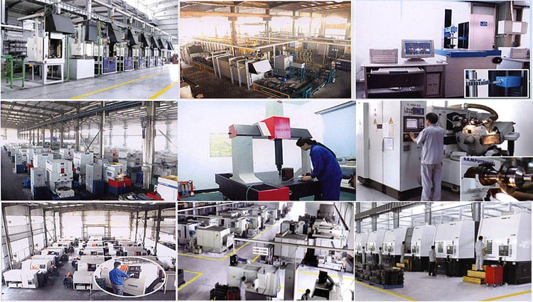 Supply information nylon Gear Coupling latest quotes


Product Description
Nylon gear flexible coupling is the latest product,it has been using by abroad,and it is designed by mechanical committee of Jinan Casting forging machinery institute.
Features of NL gear coupling:
1.Absorb parallel,angular and axial misalignments
2.Simple assembly and disassembly
3.Easy maintenance and low noise
4.High tansmission efficiency
5.Long service life
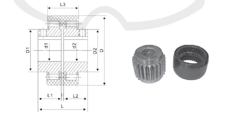
Nylon Ring Gear Coupling.
|
Tn (N.M) |
n (r/min) |
(mm) |
(KgC m 2 ) |
(Kg ) |
||||||||||
| d1 d2 |
L 1 L 2 |
L | D |
D1 D2 |
E | L3 | (mm) | (mm) | α° | |||||
| NL1 | 40 | 6000 | 6 8 10 |
16 20 25 32 |
37 45 55 69 |
40 |
26 | 4 | 34 | 2 | ±0.3 | 1° | 0.25 | 0.85 |
| 12 14 | ||||||||||||||
| NL2 | 100 | 6000 | 10 12 14 22 |
25 32 42 52 |
57 71 91 111 |
42 |
36 | 4 | 40 | 2 | ±0.4 | 1° | 0.92 | 1.7 |
| 16 18 20 24 | ||||||||||||||
| NL3 | 160 | 6000 | 20 22 24 | 52 62 |
113 133 |
66 |
44 | 4 | 46 | 2 | ±0.4 | 1° | 3.10 | 2.6 |
| 25 28 | ||||||||||||||
| NL4 | 250 | 6000 | 28 30 32 | 62 82 |
129 169 |
83 |
58 | 4 | 48 | 2 | ±0.4 | 1° | 8.69 | 3.6 |
| 35 38 | ||||||||||||||
| NL5 | 315 | 5000 | 32 35 38 | 82 112 |
169 229 |
93 |
68 | 4 | 50 | 3 | ±0.4 | 2° | 14.28 | 5.5 |
| 40 42 | ||||||||||||||
| NL6 | 400 | 5000 | 40 42 45 | 82 112 |
230 |
100 |
68 | 4 | 52 | 3 | ±0.4 | 2° | 18.34 | 6.8 |
| 48 | ||||||||||||||
| NL7 | 630 | 3600 | 45 48 50 | 82 112 |
229 |
115 |
80 | 4 | 60 | 3 | ±0.6 | 2° | 56.5 | 9.8 |
| 55 | ||||||||||||||
| NL8 | 1250 | 3600 | 48 50 55 | 112 142 |
229 289 |
140 |
96 | 4 | 72 | 3 | ±0.6 | 2° | 98.55 | 26.5 |
| 60 63 65 | ||||||||||||||
| NL9 | 2000 | 2000 | 60 63 65 | 142 172 |
295 351 |
175 |
124 | 6 | 93 | 4 | ±0.7 | 2° | 370.5 | 37.6 |
| 70 71 75 80 | ||||||||||||||
| NL10 | 3150 | 1800 | 70 71 75 80 |
142 172 212 |
292 352 432 |
220 |
157 | 8 | 110 | 4 | ±0.7 | 2° | 1156.8 | 55 |
Company Information
HangZhou EPT Couplings Co., Ltd. specializes in the research and production of expansion coupling sleeve, mechanical drives and mechanical seals. Thanks to our years of experience in research and development of couplings, and favorable conditions and dominant advantages in research and development of high-precision products and mass production, the company can meet customers’ demands.
The company has passed the certification of ISO9001-2000 Quality Management System, and realized CAD computer aided design and information management, integrating research, development and manufacturing.strives to offer products of top quality and preferential prices.
Why Choose Us???
1.High quality product—-Our tenet is “quality first”.Good material,precise
manufacturing processes and strict quality control can create excellent
quality.
2.Competitive price—-We have our own factory,scientific producing,
direct-selling.So we can save the cost and supply low price.
3.Professional—– Our professional engineer can answer technical
questions,help you solve technical problems and help you choose the
most suitable product according to your requirment.
4.Delivery fast —–We are near port,and we have professional forwarder.
Goods can be sent out within 3 to 10 working days based on order quantity.
5.Best service—–Answering e-mails or solving questions timely.
Delivery and update information on time.
Our Services
1. The questions about the coupling will be answered within 24 hours.
2. Update the procession of manufacturing.
3. Our professional engineer can answer technical questions,help you solve technical problems and help you choose the most suitable product according to your requirment.
4. Warranty 12 months: Free replacement of defective products within 12 months.

Packaging & Shipping

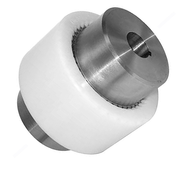

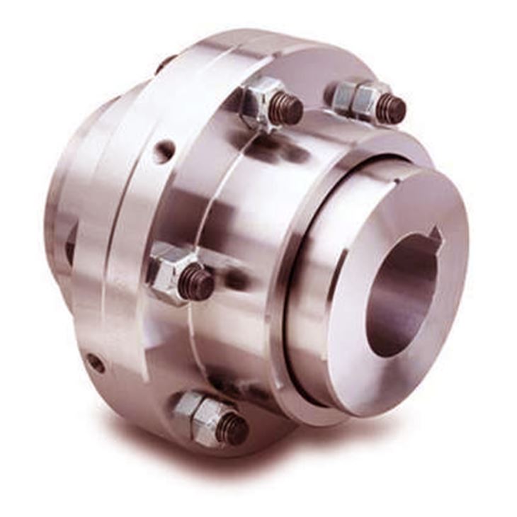

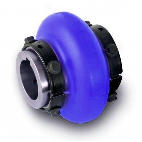
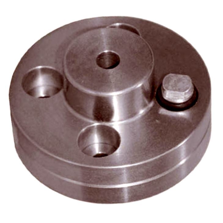
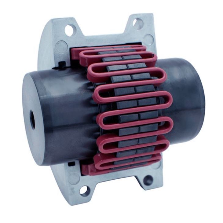
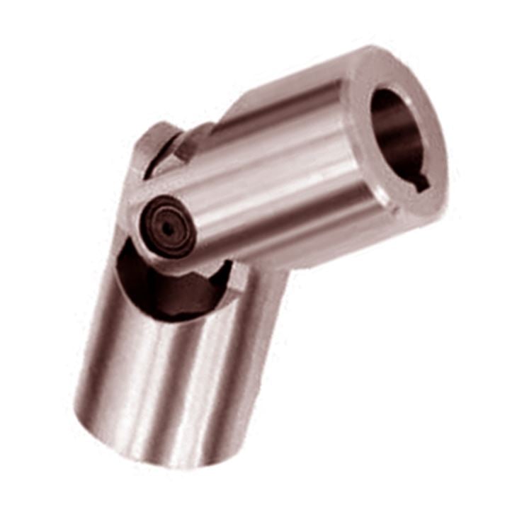


|
PACKING |
Inner Packing: Carton, Standard export packing or According to customer’s requirement Outer packing: wooden cases or According to customer’s requirement |
|
SAMPLE TIME |
5–15 days |
|
PRODUCTION TIME |
7–35 days or According to customer’s requirement |
|
DELIVERY CLAUSE |
FOB Tianjin, CFR, CIF, Express delivery |
|
PAYMENT CURRENCY |
USD |
|
PAYMENT METHODS |
T/T (30% deposit 70%against bl copy) L/C MoneyGram Other payment terms we can negotiate |
FAQ
Q1: Are you trading company or manufacturer ?
A: We are factory.
Q2:Do you provide samples ? is it free or extra ?
A: : Yes, we could offer the sample but not for free.Actually we have a very good price principle, when you make the bulk order then cost of sample will be return to you.
Q3: How long is your delivery time?
A: Generally it is 3-10 days if the goods are in stock. or it is 7-25 days if the goods are not in stock, it is according to quantity.
Q4:How long is your warranty?
A: Our Warranty is 12 month.
Q5 :Do you have inspection procedures for coupling ?
A:100% self-inspection before packing
Q6. What’s your payment?
1) 100% T/T
2) 30% in advance, others before shipment.
3) L/C
Q7:Can I have a visit to your factory before the order?
A: Sure,welcome to visit our factory.
Here is our factory address: Nancang Street, Botou, Hebei Province.


